background image

About Your Projector

18

 - ENGLISH

Preparation

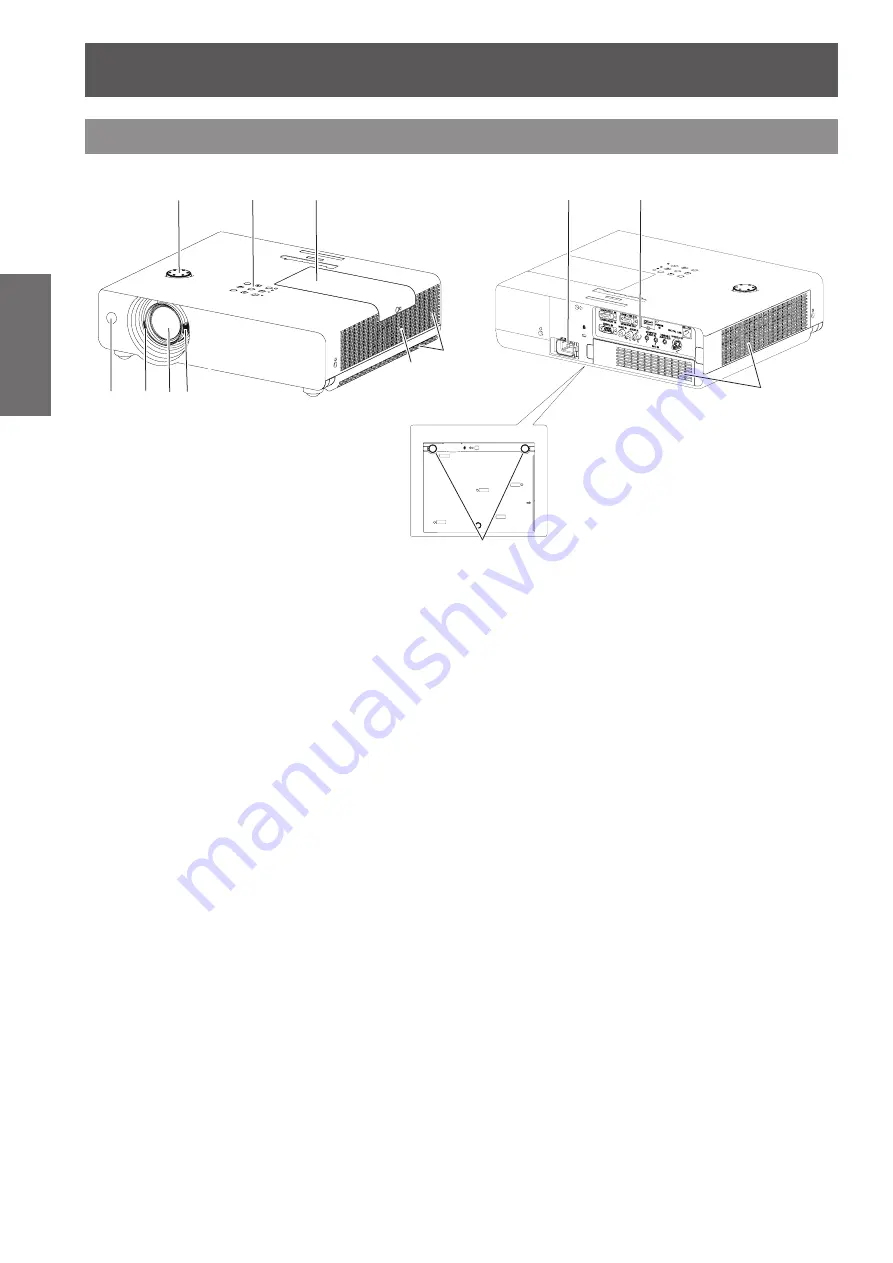
(1)    Remote control signal receiver
(2)    Focus Lever 

(

Æ

page 32)

   Adjust the focus.

(3)    Projection Lens 
(4)    Zoom Lever 

(

Æ

page 32)

   Adjust the zoom.

(5)    Vertical lens shift ring 

(

Æ

page 25)

   Adjust the vertical position of the projected   

   image. 

(6)    Control Panel and Indicators 

(

Æ

page 19)

(7)    Lamp cover 

(

Æ

page 83)


The lamp unit is located inside.

(8)    Air outlet port

  Hot air is exhausted from the exhaust vent. Do   


  not put heat-sensitive objects near this side.

(9)    Speaker
(10)  AC IN
(11)  Rear terminals 

(

Æ

page 20)

(12)  Air intake port / Air filter cover 

(

Æ

page 80)

(13)  Adjustable feet

 Adjust the projection angle.

WARNING: 

„

Keep your hands and other objects away from 

the air exhaust port

.

Keep your hand and face away.


z

Do not insert your finger.


z

Keep heat-sensitive articles away.


z

Heated air from the air exhaust port can cause burns 

or external damage.

Projector body

(5)

(4)

(1) (2) (3)

(6)

(8)

(10)

(11)

(12)

(7)

(9)

 Bottom view

(13)

Summary of Contents for PT-VW431DU

Page 1: ... Thank you for purchasing this Panasonic Product Before operating this product please read the instructions carefully and save this manual J J for future use Before using your projector be sure to read Read this first J J Æ pages 2 to 8 Model No PT VW431DU ENGLISH KL4AC ...

Page 2: ...s The exclamation point within an equilateral triangle is intended to alert the user to the presence of important operating and maintenance servicing instructions in the literature accompanying the product CAUTION This equipment is equipped with a three pin grounding type power plug Do not remove the grounding pin on the power plug This plug will only fit a grounding type power outlet This is a sa...

Page 3: ...the user is encouraged to try to correct the interference by one of the following measures Reorient or relocate the receiving antenna Increase the separation between the equipment and receiver Connect the equipment into an outlet on a circuit different from that to which the receiver is connected Consult the dealer or an experienced radio TV technician for help The user may find the booklet Someth...

Page 4: ...dust Failure to observe this will cause a fire If dust builds up on the power plug the resulting humidity can damage the insulation z z If not using the projector for an extended period of time pull the power plug out from the wall outlet z z Pull the power plug out from the wall outlet and wipe it with a dry cloth regularly Do not handle the power plug with wet hands Failure to observe this will ...

Page 5: ...ns Do not look or place your hands directly into this light z z Be especially careful not to let young children look into the lens In addition turn off the power and z z disconnect the power plug when you are away from the projector Do not insert any foreign objects into the projector Doing so will cause fire or electric shocks Do not insert any metal objects or flammable objects into the projecto...

Page 6: ...wing measures if necessary Battery fluid on your skin or clothing could result in skin inflammation or injury z z Rinse with clean water and seek medical advice immediately Battery fluid coming in contact with your eyes could result in loss of sight z z In this case do not rub your eyes Rinse with clean water and seek medical advice immediately Do not disassemble the lamp unit If the lamp breaks i...

Page 7: ...sing or internal components to deteriorate or result in fire Take particular care in locations exposed to direct sunlight or near stoves z z Always disconnect all cables before moving the projector Moving the projector with cables still attached can damage the cables which will cause fire or electric shocks to occur Never plug headphones and earphones into VARIABLE AUDIO OUT jack Excessive sound p...

Page 8: ...eferences to pages are indicated as Æ page 00 Term In these instructions the Wireless remote control unit accessory is referred to as the Remote control Brazil Only Brasil Apenas Manuseio de baterias usadas BRASIL Após o uso as pilhas e ou baterias poderão ser entregues ao estabelecimento comercial ou rede de assistência técnica autorizada Cobrir os terminais positivo e negativo com uma fita isola...

Page 9: ...hout complex cable connections The digital zoom function allows you to focus on the crucial information during a presentation The MIC function and 10 W audio output allows you to make a presentation without any external audio equipment Auto Setup Function Direct Power Off Function Improved connectivity Useful Functions for Presentations For details see the corresponding pages 1 Set up your project...

Page 10: ...TANDBY R indicator 28 Turning On the Projector 29 Enter a PIN code 30 Turning Off the Projector 31 Projecting 32 Selecting the input signal 32 How to adjust the state of the image 32 Basic operations by using the remote control 33 Using the AUTO SETUP function 33 Switching the input signal 33 Using the SCREEN button 33 Using the KEYSTONE button 34 Using the INFO button 34 Using the FREEZE function...

Page 11: ...rity 57 Fan 58 Fan control 58 Video delay control 59 Filter counter 59 Emulate 59 RS232C 60 Warning log 60 Factory default 60 Information 61 Input Source Information Display 61 Network 62 DIGITAL LINK mode 62 DIGITAL LINK setup 62 DIGITAL LINK status 62 Projector name 63 Network setup 63 Network control 64 Network status 64 AMX D D 64 RoomView 64 Extron XTP 64 Digital Interface Box 64 Network fact...

Page 12: ...quired for DIGITAL LINK connection be sure to consult J J a specialized technician or your dealer Imperfect wiring may cause poor performance of cable transmission such as distorted or choppy image and sound The interface box may not work properly due to strong radiowave from the J J broadcast station or the radio If there is any facility or equipment which outputs strong radiowave near the instal...

Page 13: ...he protection circuit of the projector Security Take safety measures against following incidents J J Personal information being leaked via this product z z Unauthorized operation of this product by a malicious third party z z Interfering or stopping of this product by a malicious third party z z Security instruction J J Æpage 57 76 Make your password as difficult to guess as possible z z Change yo...

Page 14: ...after image on the LCD panels If this happens display the all white screen in the test pattern for an hour or more Optical components J J Operating the projector in an environment with high temperature or heavy exposure to dust or tobacco smoke will reduce the service life of the optical components such as the LCD panel and polarizing plate and may necessitate their replacement within less than on...

Page 15: ...5 AC power cord holder x1 6451052124 Lens cap x1 6103594279 String x1 6103430249 Soft Carrying Case x1 6103601861 Attention After unpacking the projector discard the power cord cap and packaging material properly z z For lost accessories consult your dealer z z The part numbers of accessories and separately sold components are subject to change without notice z z Store small parts in an appropriat...

Page 16: ...ng Instructions Functional Manual Operation Manual Multi Projector Monitoring Control Software 2 7 Operation Manual Logo Transfer Software 2 0 List of compatible projector models This is a list of projectors that are compatible with the software refer to the right column and their restrictions Multi Projector Monitoring Control Software 2 7 Windows This software allows you to monitor and control m...

Page 17: ...erate the P timer function Æpage 35 15 IMAGE Button Select the image mode Æpage 36 16 MUTE Button Mute the sound Æpage 36 17 Remote control signal emitter Attention Do not drop the remote control z z Avoid contact with liquids z z Do not attempt to modify or disassemble the remote z z control Note The remote control can be used within a distance of z z about 7 m 22 97 ft if pointed directly at the...

Page 18: ...de 8 Air outlet port Hot air is exhausted from the exhaust vent Do not put heat sensitive objects near this side 9 Speaker 10 AC IN 11 Rear terminals Æpage 20 12 Air intake port Air filter cover Æpage 80 13 Adjustable feet Adjust the projection angle WARNING Keep your hands and other objects away from the air exhaust port Keep your hand and face away z z Do not insert your finger z z Keep heat sen...

Page 19: ...f life 4 WARNING indicator Indicates the abnormal conditions of the projector 5 Ambient Luminance sensor Detects room s light and select proper image quality 1 2 3 4 5 6 7 8 9 10 6 MENU button Turns the main menu on off Æpage 37 7 ENTER button Executes the selected item 8 buttons Navigates the MENU screen Adjust the volume level or mute the sound 9 INPUT button Selects the input signal Æpage 33 10...

Page 20: ...DEO input signals 8 AUDIO IN Connects the audio output signals from video equipment connected to 7 or 12 to this jack 9 COMPUTER AUDIO IN 1 Connects the audio output signals from a computer connected to 1 to this jack 10 COMPUTER AUDIO IN 2 MIC IN Connects the audio output signals from a computer connected to 2 to this jack 11 VARIABLE AUDIO OUT Outputs the audio signals input to the projector 12 ...

Page 21: ...codes ALL Code 1 Code 6 the initial ID number is ALL J J Setting the ID number 1 While holding down the MENU button press the IMAGE button The number of times you press the IMAGE button corresponds to the desired ID code number The number of times to press the IMAGE button is as follows Code 1 Once Code 2 Twice Code 3 3 times Code 4 4 times Code 5 5 times Code 6 6 times 2 The ID code is changed wh...

Page 22: ... Menu setting 1 Ceiling On Rear On Ceiling Off Rear On For details about the menu setting please refer to the Screen menu Ceiling and Rear Æ page 51 Parts for ceiling mount Optional You can install the projector on the ceiling by using the optional ceiling mount bracket ET PKV100H for high ceiling ET PKV100S for low ceiling and the optional projector mount base ET PKV200B Use only the ceiling moun...

Page 23: ...tance LT Height position H Minimum distance LW Maximum distance LT Height position H Minimum distance LW Maximum distance LT Height position H 0 76 30 0 8 1 4 0 009 0 229 0 8 1 3 0 007 0 187 0 7 1 2 0 008 0 202 1 02 40 1 1 1 8 0 012 0 305 1 0 1 7 0 010 0 249 1 0 1 6 0 011 0 269 1 27 50 1 4 2 3 0 015 0 381 1 3 2 1 0 012 0 311 1 3 2 0 0 013 0 337 1 52 60 1 7 2 8 0 018 0 457 1 6 2 5 0 015 0 374 1 5 2...

Page 24: ...in a certain error If the screen dimensions are written as SD For 4 3 aspect ratio For 16 9 aspect ratio For 16 10 aspect ratio Screen height SH SD m 0 6 SD m 0 490 SD m 0 530 Screen width SW SD m 0 8 SD m 0 872 SD m 0 848 Minimum distance LW 0 11461 SD m 0 02936 0 10402 SD m 0 02936 0 10122 SD m 0 02936 Maximum distance LT 0 18465 SD m 0 03190 0 16764 SD m 0 03190 0 16311 SD m 0 03190 ...

Page 25: ...can adjust the projection angle vertically Attention Heated air comes out of the air exhaust port while the lamp is lit Do not touch the air exhaust port directly when you adjust z z the front adjustable feet If keystone distortion occurs on the projected image perform KEYSTONE from the Screen menu z z Æpage 50 Note Screw up the adjustable feet and an audible click will be heard as the limit z z A...

Page 26: ...e with a built in time base corrector TBC or use a TBC between z z the projector and the video deck If nonstandard burst signals are connected the image may be distorted If this is the case connect a TBC between the z z projector and the video deck Note When using an HDMI cable check that it is compliant with the HDMI standard Using a cable that is not compliant with the z z HDMI standard may resu...

Page 27: ...er correctly as Picture 1 shown Attaching J J Attach the AC power cord with the power cord clamps to the projector as follows Press the clamps on its sides and then insert the AC power cord with the power cord clamps securely to the projector as Picture 2 shown It is correctly attached until you hear the CLICK sound See Picture 3 for correct attachment Removal J J Remove the AC power cord from the...

Page 28: ...d ORANGE Flashing The projector is cooling down The projector cannot be turned on until cooling is completed and the ON G STANDBY R indicator stops blinking The temperature inside the projector is abnormally high And the WARNING indicator also blinks in red Æpage 79 The projector cannot be turned on until cooling is completed and the ON G STANDBY R indicator stops blinking GREEN Lit Projecting Fla...

Page 29: ...screen please move the pointer to input source desired by pressing the and the ENTER button And then follow the input signal guidance window to correct the signal and connection If the projector is locked with a PIN code PIN code input dialog box will appear Enter the PIN code as instructed on the next page Note When the Logo select function is set to Off the logo will z z not be shown on the scre...

Page 30: ...r digit number After entering the four digit number move the pointer to Set Press the ENTER button so that you can start to operate the projector If you entered an incorrect PIN code PIN code and the number will turn red for a moment Enter the correct PIN code all over again Note If the PIN code number is not entered or wrong PIN code z z number is entered within three minutes after the PIN code d...

Page 31: ...tor cannot be turned on Wait until the ON G STANDBY R indicator stops blinking to turn on the projector again The projector can be turned on after the ON G z z STANDBY R indicator turns red The waiting time to restart will be shortened when the normal power off processing for fan cooling is completed compared with the time the AC power cord is immediately unplugged after the power off J J Direct P...

Page 32: ...imum aspect ratio under the Screen menu z z Æpage 49 How to adjust the state of the image Adjust the projection angle 1111 Place the projector parallel to the screen and then install it on a flat surface so that the screen becomes z z rectangle If the screen is tilted lower than the screen extend the adjustable feet to make a rectangle screen z z For details see Adjusting front adjustable feet z z...

Page 33: ...Computer 1 Component input DIGITAL LINK Switch to DIGITAL LINK input Note When connecting the optional z z accessory Digital Interface Box ET YFB100G to the DIGITAL LINK terminal press the DIGITAL LINK button on the remote control to switch the ET YFB100G input signal Each press of the INPUT button on the Control Panel z z of the main unit switches the settings as shown below Æpage 19 Computer 1 R...

Page 34: ...page 50 The adjustable range is limited depending on the input z z signal Using the INFO button This function allows you to display the information menu button Press INFO button on the remote control Note Press the INFO button on the remote control to z z display the first page of the information menu press again to display the second page of the menu To close the information menu press the INFO b...

Page 35: ...p Count down function button Press P TIMER button on the remote control Note To stop the count time press the P TIMER button z z To cancel the P timer function press and hold the P TIMER button Æpage 56 Using the LAMP button This function allows you to select the lamp mode for changing the brightness on the screen button Press LAMP button on the remote control Note For details see Lamp Power of Se...

Page 36: ...o select the desired image mode among Dynamic Standard Real Cinema Blackboard Green Colorboard Image 1 Image 2 Image 3 and Image 4 Note For details see Image select of Main menu z z Æpage 45 Using the MUTE button Press this button on the remote control to select On to temporarily turn off the sound button Press MUTE button on the remote control Note To turn the sound back on press this button agai...

Page 37: ...R button 3333 The submenu appears so that you can select the sub menu item Press to select the desired sub 4444 menu item Press the ENTER button or press 5555 to enter the desired item Press to set or adjust the 6666 parameter values Press to return the previous menu 7777 Press the MENU button to exit the menu display Note Some items may not be adjusted or used for certain z z signal formats input...

Page 38: ...to PC adj 42 Fine sync 43 Total dots 43 Horizontal 43 Sub menu item Factory default Page Vertical 43 Current mode 44 Clamp 44 Display area H 44 Display area V 44 Reset 44 Mode free 44 Store 44 Note This function will be available when the input source z z come from computer Image select J J Sub menu item Factory default Page Dynamic 45 Standard 45 Real 45 Cinema 45 Blackboard Green 45 Colorboard R...

Page 39: ...L LINK signal level Normal 55 Terminal Computer 2 55 Power management Shutdown 55 Direct on Off 56 Standby mode Eco 56 P timer Count up 56 Closed caption Off 57 Lamp power Normal 57 Sub menu item Factory Default Page Remote control ALL 57 Security 57 Fan L 2 58 Fan control Off 58 Video delay control Off 59 Filter counter 59 Emulate Default 59 RS232C Serial 60 Warning log 60 Factory default 60 Info...

Page 40: ...put Press to select HDMI and then press the ENTER button Video Projects the image of Video input Press to select Video and then press the ENTER button S video Projects the image of S video input Press to select S video and then press the ENTER button DIGITAL LINK Projects the image of DIGITAL LINK input Press to select DIGITAL LINK and then press the ENTER button System System is displayed below t...

Page 41: ...TSC4 43 PAL M PAL N When the projector can not project proper video image please select proper color system from the menu J J For component input Auto The projector automatically selects the scanning method of the input signal 1080i 1035i 720p 576p 480p 576i 480i When video is not being played back correctly select the correct scanning method from the menu ...

Page 42: ... adjustment parameters The adjusted parameters from the Auto PC adjustment can be stored in the projector Once the parameters are stored the setting can be done just by selecting a Mode 1 10 in the PC System Menu see page 40 See also Store on page 44 Attention Fine sync Total dots Horizontal and Vertical z z position of some computers cannot be fully adjusted with the Auto PC adjustment function W...

Page 43: ...display 2222 the adjustment dialog box Press to adjust the value 3333 The value can be adjusted from 0 to 31 z z Total dots Adjusts total number of dots in the horizontal interval Press to select Total dots 1111 Press the ENTER button to display 2222 the adjustment dialog box Press to adjust the value 3333 Horizontal Press to select Horizontal 1111 Press the ENTER button to display 2222 the adjust...

Page 44: ...display 2222 the dialog box Press to adjust the vertical area 3333 displayed by this projector Reset To reset the adjusted data all adjustments will return to their previous figures Press to select Reset 1111 Press the ENTER button 2222 A confirmation box appears and then select Yes z z Mode free Deletes the values registered in Store Press to select Mode free 1111 Press or the ENTER button to 222...

Page 45: ... image projected on a blackboard Press to select Blackboard Green and then press the ENTER button This mode helps enhance the image projected z z on a blackboard This is mainly effective on a green colored board not truly effective on a black colored board Colorboard For the image projected on a colorboard Press to select Colorboard 1111 Press or the ENTER button to 2222 display the submenu Press ...

Page 46: ...ge Press increase the brightness Maximum value 63 Press decrease the brightness Minimum value 0 Color Press to select Color 1111 Press the ENTER button to display 2222 the adjustment dialog box Press to adjust the setting value 3333 Operation Adjustment Adjustment range Press increase the intensity of the color Maximum value 63 Press decrease the intensity of the color Minimum value 0 Note When in...

Page 47: ...ment Adjustment range Press deepen green tone Maximum value 63 Press lighten green tone Minimum value 0 Blue Press to select Blue 1111 Press the ENTER button to display 2222 the adjustment dialog box Press to adjust the setting value 3333 Operation Adjustment Adjustment range Press deepen blue tone Maximum value 63 Press lighten blue tone Minimum value 0 Daylight View This function uses an ambient...

Page 48: ...tion can not be selected when 480p 576p z z 720p 1035i 1080i D 480p D 576p D 720p D 1035i D 1080i or D 1080p is selected in System Menu Progressive An interlaced video signal can be displayed in progressive mode Press to select Progressive 1111 Press the ENTER button to display 2222 the dialog box Press to select the desired item 3333 Off Disabled L 1 For an active picture L 2 For a still picture ...

Page 49: ...size is larger than the panel size the projector enters to the panning mode automatically Press to select True and then 1111 press the ENTER button Press to pan the image 2222 When adjusted the arrows will turn red When z z reached to the correction limits the arrows will disappear Note When input computer signal to the projector True will z z be available Projector image may be distorted due to d...

Page 50: ... by pressing the D ZOOM or the ENTER button To exit the Digital zoom mode press any button except the D ZOOM ENTER and buttons To return to the previous screen size select a screen size from the Screen Size Adjustment Menu or select an input source from the Input Source Selection Menu Æpage 40 again or adjust the screen size with the D ZOOM buttons Note When input computer signal to the projector ...

Page 51: ...ht reversed Screen aspect This function is used to project the image to a 4 3 or 16 9 projection screen Press to select Screen aspect 1111 and then press the ENTER button Press to choose one from the 2222 items as below Default 16 10 16 10 is the aspect of the LCD panel 16 9 Set to a 16 9 projection screen 4 3 Set to a 4 3 projection screen Note When the 4 3 function is selected Natural wide is no...

Page 52: ...MIC the MIC gain z z is not available Connect the computer 2 audio input signals to z z COMPUTER AUDIO IN 1 terminal as the MIC function is turned on If the MIC function is turned on when z z connecting PC audio to the AUDIO IN a mini jack loud sound may be output suddenly depending on the setting value of MIC gain MIC gain Press to select MIC gain and 1111 then Press the ENTER button Press to adj...

Page 53: ...Input search This function detects the input signal automatically When a signal is found the search will stop Off Input search will not work On 1 Input search works 1 On 2 Input search works 2 When pressing the AUTO SETUP button on the remote control or the control panel When turning on the projector by pressing the button on the remote control or the control panel When pressing the AUTO SETUP but...

Page 54: ...J J This function decides on the starting up display from among following options Off Show the countdown display only Default Show the factory set logo User The logo transferred by Logo Transfer Software 1 is projected Logo Transfer Software is included on the supplied CD ROM Logo PIN code lock J J This function prevents an unauthorized person from changing the screen logo Off The screen logo can ...

Page 55: ...NK signal level To set the signal level when the DIGITAL LINK input is selected Press to select DIGITAL LINK 1111 signal level and then press the ENTER button Press to switch the item 2222 Normal When the output of external equipment connected to DIGITAL LINK terminal is set to Standard Enhanced When the output of external equipment connected to DIGITAL LINK terminal is set to Enhanced Note The op...

Page 56: ...he projector even if the projector is turned off If Standby mode is set to Eco you cannot use network z z functions when the projector is standing by Also you cannot use some RS 232C protocol commands If set to Network you can use network functions when z z the projector is standing by If Standby mode is set to Eco the signal come from z z MONITOR OUT and VARIABLE AUDIO OUT terminals are unavailab...

Page 57: ...P button to z z display Lamp power Normal Normal brightness Eco Lower brightness reduces the lamp power consumption and extends the lamp life Note If Lamp power is set to Normal and the operating z z environment temperature exceeds 35 C 95 F Lamp power may be changed to Eco automatically Remote control This switching function prevents remote control interference when operating several projectors o...

Page 58: ... all over again PIN code change J J The PIN code can be changed to your desired four digit number Press to select PIN code change 1111 and then Press ENTER button Current Pin code dialog box appears z z Press to enter the current code 2222 Press button to fix the number and move the red frame pointer to the next box The New PIN code input dialog box appears z z Repeat these steps to set a new PIN ...

Page 59: ...Another confirmation dialog box appears select Yes to reset the Filter counter Emulate When using the control commands for one of our projectors that you have previously purchased to control this projector using a computer via its SERIAL IN terminal set up the Emulate function as follows This will allow you to use the control software etc designed for our existing projectors Press to select Emulat...

Page 60: ...ital interface box LAN cable straight Digital interface box ET YFB100G Communication cable Warning log This function records anomalous operations while the projector is in operation and use it when diagnosing faults Press to select Warning log 1111 Press or the ENTER button to 2222 display the latest warning message Up to 10 warning logs are displayed with the z z latest warning message at the top...

Page 61: ...ntal frequency of the input signal is displayed in kHz or kHz when no signal V sync freq J J The selected V sync freq is displayed The vertical frequency of the input signal is displayed in Hz or Hz when no signal Screen J J The selected Screen size is displayed Language J J The selected language is displayed Lamp power J J The selected lamp mode is displayed Lamp runtime J J The cumulative lamp o...

Page 62: ...GITAL LINK 1111 setup Press ENTER button or the button 2222 to access to the submenu Duplex Ethernet J J Set the method of communication of the computer or hub Press to select Duplex Ethernet 1111 and press ENTER button Press to switch the settings 2222 Autonegotiation Communication method will be set automatically 100 Base TX Full Full Duplex communication method will be set 100 Base TX Half Half...

Page 63: ... Normal signal received 11 8 dB Yellow Part of the received data destroyed more than 7 dB Red Abnormal signal received Projector name You can change the projector name to be displayed on the network Press to select Projector name 1111 and press ENTER button Select characters with the 2222 buttons and press the ENTER button to enter the projector name Select BS to delete one character selected with...

Page 64: ...m a computer This projector supports Crestron RoomView For details of Crestron RoomView refer to the Crestron z z Electronics Inc website Provided only in English http www crestron com For the download of RoomView Express refer to the Crestron Electronics Inc website Provided only in English http www crestron com getroomview Extron XTP To carry out connection settings with XTP Transmitter made by ...

Page 65: ...nnections A Web browser is required to use this function Confirm that the Web browser can be used beforehand z z Compatible OS Windows XP Windows Vista Windows 7 Mac OS X v10 4 v10 5 v10 6 v10 7 Compatible Web Browser Internet Explorer 7 0 8 0 9 0 Safari 4 0 5 0 Mac OS Communication with an E mail server is required to use the E mail function Confirm that the E mail can be z z used beforehand Use ...

Page 66: ...tor is used in the middle measure in a condition that the relay connector is included Do not use the switching hub between the Twisted pair cable Extender and the projector z z When connecting to the projector using the Twisted pair cable Extender receiver of other maker do not use z z another Twisted pair cable Extender between the Twisted pair cable Extender of other maker and the projector The ...

Page 67: ...ser name and Password z z The factory default settings are user1 user privileges or admin1 administrator privileges for the user name and panasonic lowercase letters for the password Click OK to display the Projector 4444 status page z z Projector status page is displayed Note Avoid activating two or more Web browser simultaneously to work out setting or control actions z z Change the password fir...

Page 68: ...tus page J J Click Status then Projector status to display the Status information page This page displays the projector statuses established for the items shown below 1 Displays the type of projector 2 Displays the firmware version of the projector main unit 3 Displays the power source status 4 Displays the video mode status 5 Displays the serial number of the projector 6 Displays the firmware ver...

Page 69: ...a heating device etc the air intake is blocked or the air filter is clogged EXHAUST AIR TEMPERATURE Exhaust air temperature is high Exhaust may be blocked or Fan control mode may be set wrong Æpage 58 OPTICS MODULE TEMPERATURE Optics module temperature is high LAMP REMAIN TIME The lamp runtime has exceeded the prescribed cumulative time and it is now time to replace the lamp LAMP STATUS The lamp h...

Page 70: ...o select the input signals 3 Volume adjust 4 Switches image mode 5 Operation of AV mute 5 4 3 2 1 Detail control page J J Click Projector control then Advanced control to display the Detail control page 1 Execute Auto setup function 2 Operations on Screen mode 3 Operations on Keystone function 4 Operations on Rear Ceiling 5 Operations on Image adjust 1 2 3 4 5 ...

Page 71: ...red Settings performed here are the same as the settings performed with the Network menu of the projector Click Submit 4444 z z The settings will be registered Note Changing the setting of LAN while connected with z z LAN might disconnect the connection Ping test page J J This page makes it possible to check whether the network is connected to the e mail server POP server DNS server etc Click Deta...

Page 72: ...r so that the recipient may easily identify the originator of the e mail maximum 63 characters 5 The user can modify the minimum time interval of temperature warning mail The default value is 60 minutes In this case the user cannot send another mail for 60 minutes after sending previous temperature warning mail even the set warning temperature is reached again 6 Select the temperature of the intak...

Page 73: ...ge when POP SMTP authentication is required for mail transmissions Click Detailed set up then Authentication set up to display the Authentication server setup page 1 Select the authentication method specified by your Internet service provider 2 Set this if SMTP authentication has been selected 3 Enter the IP address or server name of the POP server The DNS server must be set if the server name is ...

Page 74: ...ERATURE OFF check system FAN OK INTAKE AIR TEMPERATURE OK EXHAUST AIR TEMPERATURE OK OPTICS MODULE TEMPERATURE OK LAMP REMAIN TIME OK LAMP STATUS OK APERTURE CONTRAST SHUTTER OK Error code 00 00 00 00 00 00 00 00 Intake air temperature 31 degC 87 degF Exhaust air temperature 37 degC 98 degF Optics module temperature 39 degC 102 degF PROJECTOR RUNTIME 1 H LAMP ECO 500 H LAMP NORMAL 300 H LAMP REMAI...

Page 75: ...ke air temperature 31 degC 87 degF Exhaust air temperature 37 degC 98 degF Optics module temperature 39 degC 102 degF PROJECTOR RUNTIME 1 H LAMP ECO 500 H LAMP NORMAL 300 H LAMP REMAIN 2400 H Current status MAIN VERSION 1 00 NETWORK VERSION 1 00 LAMP STATUS LAMP OFF INPUT NETWORK Wired Network configuration DHCP Client OFF IP address 192 168 10 100 MAC address 04 20 9A 00 00 00 Memo Command port s...

Page 76: ...count 1 Displays the account to change 2 New user name input field 3 New password input field 4 New password input field re enter for confirmation 5 Button for executing password change Change Password page with the user rights Only the change of password is enabled under the user rights 1 Current password input field 2 New password input field 3 New password input field re enter for confirmation ...

Page 77: ...t available 4 Input Select Sets the input selection When the power of the projector is turned off this operation is not available 5 Operation buttons on the menu screen Operates on the menu screen 6 Freeze image quality adjustment Sets freeze image quality details 7 Back Returns to the previous page Tools page Click Tools on the operation page 1 Control system Sets the information required for the...

Page 78: ...ted value 5 Power Status Displays the status of the power 6 Source Displays the selected video input 7 Projector Position Displays the projection method of the projector 8 Lamp Mode Displays the lamp mode 9 Error Status Displays the error status 10 Exit Return the operation page Help page Click Help on the operation page The Help Desk screen is displayed 1 Help Desk Sends or receive messages to th...

Page 79: ... even higher the WARNING indicator will flash faster and the ON G STANDBY R indicator blinks in orange When the projector has cooled inside and returned to operating temperature it will turn off automatically Check Unplug the AC power cord and plug it again to turn on the projector Did you provide appropriate space for the projector to be ventilated Check the installing condition to see if the air...

Page 80: ...Wipe off the dirt and dust off the front surface of the lens with soft clean cloth Do not use a cloth that has an abrasive surface or a cloth that is moist oily or covered with dust z z Do not use excessive force when wiping the lens as it is fragile z z Attention The lens is made of glass Impacts or excessive force when wiping may scratch its surface z z Please handle with care Replacing the unit...

Page 81: ...before you replace the air filter units z z When attaching the air filter unit make sure that the projector is stable and work in an environment that is z z safe even in the event of the air filter unit dropping Do not operate the projector with the air filter units removed Dust may accumulate on the optical elements z z degrading picture quality Do not put anything into the air vents Doing so may...

Page 82: ...opened If pieces of glass get into your eyes or mouth seek medical advice immediately The lamp contains mercury Consult your local municipality or your dealer about correct disposal of used z z lamp units Attention Do not use other than designated lamp units z z The part numbers of accessories and separately sold components are subject to change without notice z z When to replace the lamp unit J J...

Page 83: ...2 lamp cover fixing screw and remove the lamp cover Remove the lamp cover by pulling it slowly z z toward the direction of the arrow Use a Phillips screwdriver to loosen the 3333 three lamp unit fixing screws until the screws turn freely Hold the used lamp unit by its handles and pull it gently from the projector Insert the new lamp unit in correct 4444 direction Tighten the three lamp unit fixing...

Page 84: ...f time attach the lens cap To prevent loss for the lens cap please according to the following procedures attach the lens cap with the string of accessories Thread the thinner end of the string through 1111 the hole on the lens cap Thread the other end of the string through 2222 the hole on the bottom of the projector Lens cap String ...

Page 85: ...Tint adjustment may be incorrect z z 46 The input source which is connected to the projector may not be z z adjusted correctly RGB cable is damaged z z No sound from the internal speaker The input terminals may not have been correctly connected z z 26 The volume may have been set to the minimum level z z 35 52 The AV mute function may have been turned on z z 35 When the VARIABLE AUDIO OUT is plugg...

Page 86: ...le to COMPUTER AUDIO IN 2 terminal and set to Computer 2 in Sound of Setting menu 55 The image is distorted or runs off Check PC adj or Screen and adjust them z z 43 49 The exclamation mark appears on the screen Your operation is invalid Operate correctly z z No picture or sound is output from DIGITAL LINK input Is the cables securely connected between the Twisted pair cable z z Extender and the i...

Page 87: ...byte Indicates other errors range 0 2 Definitions for each value from 0 to 2 are as follows 0 No error known 1 Warning 2 Error LAMP Lamp status query Parameters 1st digits 1 5 digits Lamp cumulative operating time 2nd digit 0 Lamp off 1 Lamp on INST Input selection list query The followings are returned as parameters 11 12 13 21 22 23 31 32 NAME Projector name query The name set for Projector name...

Page 88: ...e Mode 1 Protect mode Generate a 32 byte hash value from the following data using MD5 algorithm 3333 xxxxxx yyyyy zzzzzzzz xxxxxx Administrator rights user name for WEB CONTROL Default user name is admin1 yyyyy Password of above administrator rights user Default password is panasonic zzzzzzzz 8 byte random number obtained in Step 2 Command transmission method z z Transmit using the following comma...

Page 89: ... Response data Data section Blank Mode Termination symbol NTCONTROL ASCII string 0x20 0 0x30 CR 0x0d 9 bytes 1 byte 1 byte 1 byte Mode 0 Non protect mode Command transmission method z z Transmit by the following command format Transmitted data Header Data section Termination symbol 0 0x30 0 0x30 Control command ASCII string CR 0x0d 1 byte 1 byte Undefined length 1 byte Receive data Header Data sec...

Page 90: ...al name Contents NC TXD Transmitted data RXD Received data NC GND Earth NC CTS Connected internally RTS NC Communication conditions J J Signal level RS 232C compliant Character length 8 bits Sync method Asynchronous Stop bit 1 bit Baud rate 9 600 bps X parameter None Parity None S parameter None Note The serial control cannot be used when RS232C is set to DIGITAL LINK z z The Baud rate of PT VW430...

Page 91: ... colon is not necessary J J Basic format with sub command STX C1 C2 C3 ETX S1 S2 S3 S4 S5 E P1 P2 P3 P4 P5 P6 When transmitting a command which does not need a parameter the operation E and parameter are not necessary End 1 byte Parameter undefined length Colon 1 byte 3 command characters 3 bytes Start 1 byte Parameter 6 bytes Symbol or 1 byte and set value or adjustment value 5 bytes Operation 1 ...

Page 92: ...AL LINK When Digital interface box Optional accessory ET YFB100G is connected to DIGITAL LINK terminal and INPUT is selected to DIGITAL LINK terminal and Digital interface box at the same time Parameter DL1 VID Video DL1 SVD S video DL1 PC1 Computer 1 RGB DL1 PC2 Computer 2 RGB DL1 HD1 HDMI 1 DL1 HD2 HDMI 2 OSH AV mute function Turning off the projection and sound temporarily Sending the command s...

Page 93: ...C data HD SYNC VD DDC clock Pin assignments and signal names of COMPUTER 2 IN MONITOR OUT J J terminal Outside view Pin No Signal names Not assigned GND terminals R G B HD SYNC VD Pin assignments and signal names of HDMI IN terminal J J Outside view Pin No Signal names Pin No Signal names T M D S data 2 T M D S clock shield T M D S data 2 shield T M D S clock T M D S data 2 CEC T M D S data 1 T M ...

Page 94: ...4 250 A 1080i 1 920 x 1 080i 33 750 60 000 74 250 A 28 125 50 000 74 250 A VGA 640 x 400 31 470 70 090 25 175 A C 640 x 480 31 470 59 880 25 149 A 37 860 72 810 31 500 A 37 860 74 380 31 500 A 37 500 75 000 31 500 A 43 269 85 000 36 000 A 720 x 400 31 470 70 090 28 322 A SVGA 800 x 600 32 700 51 090 32 700 A 34 500 55 380 36 432 A 35 156 56 250 36 000 A 38 600 60 310 38 600 A 37 880 60 320 40 000 ...

Page 95: ...86 960 44 900 A 36 000 87 170 47 300 A SXGA 1 152 x 864 64 200 70 400 94 560 A 1 152 x 900 61 200 65 200 92 000 A 61 850 66 000 94 500 A 71 400 75 600 105 100 A 1 280 x 960 60 000 60 000 108 000 A 1 280 x 1 024 62 500 58 600 108 000 A 63 340 59 980 108 180 A 63 900 60 000 107 350 A 63 370 60 010 111 520 A 63 740 60 010 109 497 A 63 980 60 020 108 000 A 63 790 60 180 108 190 A 71 690 67 190 117 004...

Page 96: ...000 100 190 A 1 376 x 768 48 360 60 000 86 670 A WSXGA 1 680 x 1 050 65 290 59 954 146 250 A WXGA 1 440 x 900 55 935 59 887 106 500 A 74 918 60 000 161 850 A WUXGA 1 920 x 1 200 74 556 59 885 193 250 A 74 038 59 950 154 000 A D VGA 640 x 480 31 470 59 940 25 175 A H D 480p 31 470 59 880 25 200 A D 576p 768 x 576 31 250 50 000 29 500 A D 720p 1 280 x 720 37 500 50 000 74 250 AA 45 000 60 000 74 250...

Page 97: ...0 59 954 146 250 A D WUXGA 1 920 x 1 200 74 038 59 950 154 000 A i added to the resolution value indicates an interlaced signal Picture quality is indicated by the following symbols AA Maximum picture quality can be obtained A Signals are converted by the image processing circuit Where marked signals indicates in Plug and Play is compatible with EDID of projector Unmarked signals in Plug and Play ...

Page 98: ...080 60i Horizontal 33 75 kHz Vertical 60 Hz 1125 1080 50i Horizontal 28 13 kHz Vertical 50 Hz HD SYNC and V terminals are not compliant with 3 value composite SYNC z z for Video signal including S video Horizontal 15 75 kHz 15 63 kHz Vertical 60 Hz 50 Hz for HDMI signal 525p 480p 625p 576p 750 720 60p 750 720 50p 1125 1080 60i 1125 1080 50i 1125 1080 24p 1125 1080 60p 1125 1080 50p Displayable res...

Page 99: ...4 Cabinet Molded plastic Dimensions Width 379 mm 14 92 Height 107 mm 4 21 when front adjustable feet shortened Depth 305 mm 12 01 excluding protractions Weight Approx 4 8 kg 10 58 lbs 5 Operating environment Operating environment temperature 6 0 C 32 F to 40 C 104 F Elevation below 1 200 m Fan control Off 0 C 32 F to 30 C 86 F Elevation 1 200 m 2 000 m Fan control On 1 0 C 32 F to 30 C 86 F Elevat...

Page 100: ...which is not purchased from an authorized distributors or environmental conditions Remove an unused ceiling mount bracket promptly z z Ensure to use a torque driver and do not use an electrical screwdriver or an impact screwdriver z z For details see the work instruction manual packed together with the ceiling mount bracket z z The model Nos of the accessories and the parts sold separately are sub...

Page 101: ...ect 45 Information 61 Input menu 40 Input search 53 Installing and Removing batteries 21 In standby mode 52 Iris 46 K Keystone 34 50 L LAMP indicator 79 Lamp power 57 Lamp unit 82 Language 53 List of compatible signals 94 Logo 54 M Main menu 38 Maintenance 80 Managing the indicated problems 79 Manual PC adjust 43 Menu Navigation 37 Menu position 53 MIC 52 Mute 52 N Natural wide 49 Network 62 Netwo...

Page 102: ...to discard this product please contact your local authorities or dealer and ask for the correct method of disposal Panasonic Systems Communications Company of North America One Panasonic Way 2F 13 Secaucus NJ 07094 TEL 877 803 8492 Panasonic Canada Inc 5770 Ambler Drive Mississauga Ontario L4W 2T3 TEL 905 624 5010 Panasonic Corporation Panasonic Corporation 2012 Web Site http panasonic net avc pro...

Reviews: