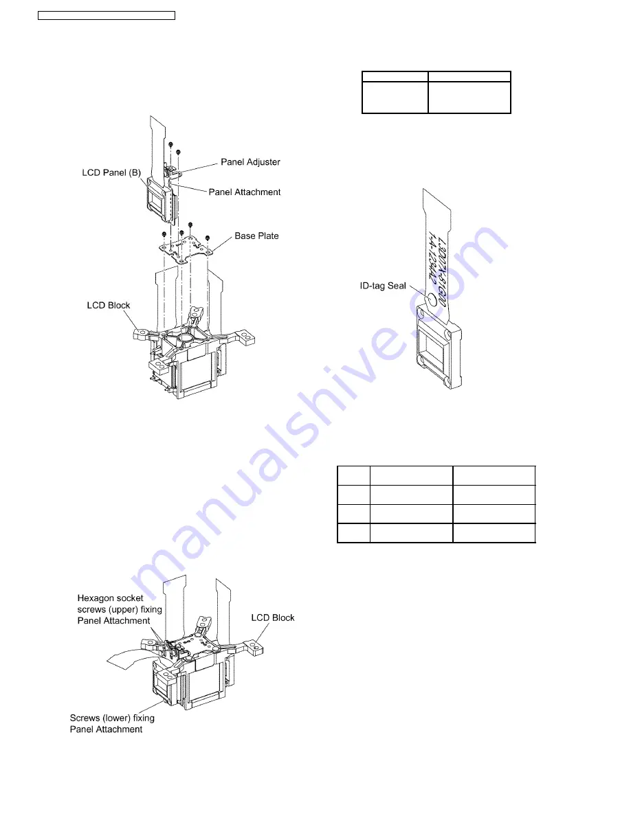
shifted by your fingers.
Note:
·
The panel adjustment fittings set (panel attachment,
panel adjuster and base plate) is an option for
service.
6. Reassemble
the
projector
in
the
reverse
order
of
disassembling, but leave the upper case and the screws
fixing the A-P.C.Board block as they are removed.
7. Adjust the convergence according to the section 8.4.
"Convergence Adjustment".
8. After the adjustment, while paying attention not to vary the
adjusting result, tighten the 2 screws fixing the panel
attachment with a hexagon head wrench.
Notes:
·
Prepare a hexagon head wrench processed short.
9. Remove the LCD block again.
10. Tighten the 3 screws fixing the panel attachment.
11. Reassemble the projector as it was.
7.20. LCD Panel Discrimination
ID-tag seal color
LCD panel
Red
LCD panel (R)
Blue
LCD panel (B)
(No seal)
LCD panel (G)
·
Since the ID-tag seal is pasted to the FPC of LCD Panel,
(R), (G) or (B) can be easily identified by the color of the
seal.
·
Finally, identify the panel color by the part number printed
on the FPC.
7.21. LCD Panel Combination
·
Part number is printed on the FPC of LCD Panel.
·
When replacing LCD Panel, use a component which has
the same part number as the original.
LCD
panel
Combination1
Combination2
R
L5BDAYY00062
(L3D07X-81G00)
L5BDAYY00065
(L3D07X-82G00)
G
L5BDAYY00066
(L3D07X-82G00)
L5BDAYY00063
(L3D07X-81G00)
B
L5BDAYY00064
(L3D07X-81G00)
L5BDAYY00067
(L3D07X-82G00)
7.22. Replacement of Incidence
Polarizer (G)
1. Remove the A-P.C.Board block according to the steps 1
through 4 in the section 7.3. "Removal of A-P.C.Board".
2. Mark positions of the incidence polarizer (G).
Note:
·
Mark accurately as possible because the marks will
be
used
for
resetting
the
incidence
polarizer
position.
3. Unscrew the 1 screw and remove the incidence polarizer
(G).
4. Attach a new incidence polarizer (G) and align it with the
mark.
5. Tighten the 1 screw with care not to move the incidence
polarizer position.
20
PT-FW100NTU / PT-FW100NTE / PT-FW100NTEA
Summary of Contents for PT-FW100NTE
Page 2: ...2 PT FW100NTU PT FW100NTE PT FW100NTEA ...
Page 3: ...3 PT FW100NTU PT FW100NTE PT FW100NTEA ...
Page 9: ...3 2 Self Check Display and Contents 9 PT FW100NTU PT FW100NTE PT FW100NTEA ...
Page 31: ...9 Troubleshooting 31 PT FW100NTU PT FW100NTE PT FW100NTEA ...
Page 32: ...32 PT FW100NTU PT FW100NTE PT FW100NTEA ...
Page 33: ...33 PT FW100NTU PT FW100NTE PT FW100NTEA ...
Page 34: ...34 PT FW100NTU PT FW100NTE PT FW100NTEA ...
Page 35: ...35 PT FW100NTU PT FW100NTE PT FW100NTEA ...
Page 36: ...36 PT FW100NTU PT FW100NTE PT FW100NTEA ...
Page 37: ...37 PT FW100NTU PT FW100NTE PT FW100NTEA ...
Page 38: ...38 PT FW100NTU PT FW100NTE PT FW100NTEA ...
Page 39: ...39 PT FW100NTU PT FW100NTE PT FW100NTEA ...
Page 40: ...40 PT FW100NTU PT FW100NTE PT FW100NTEA ...
Page 41: ...41 PT FW100NTU PT FW100NTE PT FW100NTEA ...
Page 42: ...42 PT FW100NTU PT FW100NTE PT FW100NTEA ...
Page 43: ...43 PT FW100NTU PT FW100NTE PT FW100NTEA ...
Page 44: ...44 PT FW100NTU PT FW100NTE PT FW100NTEA ...
Page 51: ...12 Schematic Diagram PT FW100NTU PT FW100NTE PT FW100NTEA 51 ...
Page 66: ...PT FW100NTU PT FW100NTE PT FW100NTEA 66 ...
Page 67: ...14 Terminal guide of ICs and transistors PT FW100NTU PT FW100NTE PT FW100NTEA 67 ...
Page 68: ...15 Exploded Views PT FW100NTU PT FW100NTE PT FW100NTEA 68 ...
Page 69: ...PT FW100NTU PT FW100NTE PT FW100NTEA 69 ...
Page 70: ...PT FW100NTU PT FW100NTE PT FW100NTEA 70 ...
Page 71: ...PT FW100NTU PT FW100NTE PT FW100NTEA 71 ...
Page 86: ......
Page 87: ......
Page 88: ......
Page 89: ......
Page 90: ......
Page 91: ......
Page 92: ......
Page 93: ......
Page 94: ......
Page 95: ......
Page 96: ......
Page 97: ......
Page 98: ......
Page 99: ......
Page 100: ......
Page 101: ......


