18
7.1.5.
Bottle Mode
7.1.6.
Alarm Mode
Features :
• Drinks can be cooled quickly in the freezer.
• This mode has a timer function, and can be set to beep when the timer reaches 5, 10, 15, 20,
25 or 30 minutes.
• Remove the bottles when the beep is heard. If bottles are left in the freezer for a long time,
their contents could freeze and the bottles might break.
Settings :
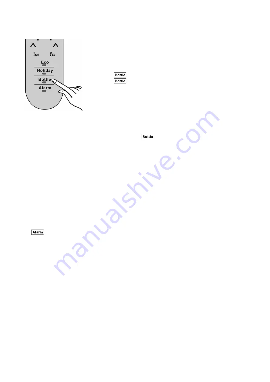
1. Press
once and Bottle mode indicator lights.
2. Press
again until the desired time is displayed.
The set time is shown as follows by the indicators.
First indicator lights : 5 min First and second indicators light : 10 min
First to third indicators light : 15 min First to fourth indicators light : 20 min
First to fifth indicators light : 25 min First to sixth indicators light : 30 min
One indicator represents five minutes.
3. If no operation is performed for 1 second (3 sec for the first press) during the setting pro-
cess, the Bottle mode indicator will flash and a beep will be heard indicating that Bottle
Mode is set.
4. The top lit indicator blinks for five minutes. Then it becomes unlit and the next highest
indicator starts blinking. This repeats until the last indicator has blinked for five minutes.
5. When the set time comes, a beep will be heard.
• To end Bottle mode, press
.
The Bottle mode indicator flashes and a beep will be heard indicating that Bottle mode has
been ended.
Notes:
• When using this mode, check the temperature of the bottles regularly.
• When the bottles have cooled sufficiently, remove them from the freezer.
Features :
• An alarm will be heard:
- when any problem occurs in the refrigerator.
- when the voltage is low.
- when the fridge door is left ajar.
Settings :
• Press
to stop the beep.
Summary of Contents for NR-B32SG1
Page 2: ...2 1 Safety Precautions ...
Page 3: ...3 ...
Page 4: ...4 ...
Page 6: ...6 3 General Introduction 3 1 Flow of Refrigerant ...
Page 7: ...7 3 2 Flow of Air 3 2 1 Inside the Fridge 3 2 2 Flow of Air Through Air Ducts Front view ...
Page 12: ...12 5 Location of Controls and Components 5 1 Display and Control Panel ...
Page 13: ...13 5 2 Components ...
Page 24: ...24 9 Troubleshooting Guide ...
Page 25: ...25 ...
Page 26: ...26 ...
Page 30: ...30 4 Disconnect all socket connections 5 Remove the main pcb box and take out the main PCB ...
Page 36: ...36 How to replace fan motor Summary ...
Page 74: ...74 12 Dimensions ...


