33
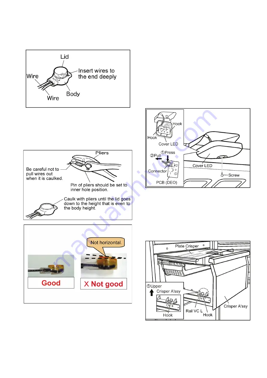
a. Insert deeply each wire one by one in Scotch Lock.
• Scotch lock is a parts that can connect with non-
stripped wires. No need to strip wire beforehand.
When stripped wire is connected with scotch lock, it
will come off.
b. The lid (color painted) of the Scotch Lock is caulked
with pliers. Then the lid height become in the same of
the body height of the Scotch Lock.
• When scotch lock is caulked with pliers, be sure to
caulk while pushing lead wires towards back side.
Otherwise an electric circuit will not be connected
properly.
c. After caulking with pliers 2 or 3 times, check if it is
fixed by pulling lead wires.
CAUTION
Be careful not to be bite the wires by Sensor PC
Cover, when store the wires and the Scotch Lock in it.
11.2. Disassembly of VC (Vegetable
Compartment)
11.2.1. PCB (VC)
1. Remove Crisper A'ssy and Plate Crisper
• Pull Crisper Case, take it out from each two portions of
Rail VC right and left.
• Pull Plate Crisper from upper side in VC.
-You can see the figure (11.2.2.(1)).
2. Remove the screw that is fixation of Cover LED on upper
side of VC. Then remove Cover LED.
3. Remove PCB (VC) while pressing left and right hooks of
reverse side of Cover LED.
4. Pull the connector out while pressing the hook.
NOTES
• Be careful not to break PCB (VC) when it is removed and
installed.
11.2.2. CRISPER A’SSY and Plate Crisper
1. Remove Crisper A'ssy and Plate Crisper.
• Pull Crisper Case, take it out from each two portions of
Rail VC right and left.
• Pull Plate Crisper from upper side in VC.
Summary of Contents for NR-B32FW3
Page 6: ...6 3 General Introduction 3 1 Flow of Refrigerant And Air ...
Page 7: ...7 4 Features 4 1 Features 4 1 1 High Efficiency Cabinet ...
Page 8: ...8 4 1 2 Storage Solution ...
Page 9: ...9 4 1 3 Refrigerator Compartment 4 1 4 Hygiene Active and Multi Airflow ...
Page 10: ...10 4 1 5 Vegetable Case 4 1 6 Vitamin Safe ...
Page 11: ...11 4 1 7 Hygiene Active ...
Page 18: ...18 6 2 Components ...
Page 19: ...19 7 Installation Instructions 7 1 Installation Instructions ...
Page 20: ...20 ...
Page 21: ...21 7 2 Setting the temperature ...
Page 22: ...22 7 3 Using the handy functions ...
Page 27: ...27 10 Troubleshooting Guide 10 1 FC and PC not cooling at all Compressor does not run ...
Page 28: ...28 10 2 PC is not cooling or poor cooling FC cooling condition is normal ...
Page 29: ...29 10 3 FC is poor cooling Compressor run ...
Page 30: ...30 10 4 VC is poor cooling or excessive cooling ...
Page 48: ...48 12 Maintenance ...
Page 49: ...49 ...
Page 50: ...50 ...
Page 51: ...51 13 Dimensions 13 1 Outside ...
Page 52: ...52 13 2 Inside ...


