9.3. Low voltage transformer
and/or power relays (RY1,
RY2)
NOTE:
Be sure to ground any static electric charge built up on
your body before handling the DPC.
(A) Using solder wick or a desoldering tool and 30W soldering
iron, carefully remove all solder from the terminal pins of the
low voltage transformer and/or power relays.
NOTE:
Do not use a soldering iron or desoldering tool of more
than 30 watts on DPC contacts.
(B) With all the terminal pins cleaned and separated from DPC
contacts, remove the defective transformer/power relays
making sure all terminal pins are inserted completely. Resolder
all terminal contacts carefully.
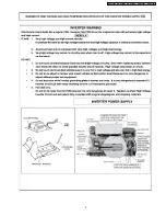
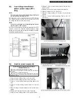
9.4. Inverter power supply (U)
CAUTIONS WHILE REPLACING INVERTER
POWER SUPPLY (U)
1. Make sure to leave the grounding plate in its place.
2. Make sure to securely tighten grounding screw from the bottom of
chasis (base).
3. Securely connect 3 lead wire connectors.
4. Make sure the heat sink has enough space (gap) from the oven.
Take special care not to touch any lead wire to the aluminum heat
sink because it is hot.
1. Remove 1 screw holding orifice on the cover plate.
2. Remove 1 screw holding top front cover on the oven.
3. Remove 1 screw holding Inverter grounding plate on the
oven.
4. Remove 3 screws holding Inverter bracket on top front
cover.
5. Slide 2 locking of Inverter bracket at the top front cover
slightly.
6. Disconnect 2 lead wires from fan motor A terminals.
7. Remove 1 screw holding orifice on the Inverter bracket.
8. Release 2 tabs to make Inverter bracket flat, and then
remove orifice.
9. Release 2 tabs on the Inverter bracket and make flat.
10. Unplug 3 connector on H.V. Inverter (U).
11. Remove 3 screws holding H.V. Inverter (U) onto Inverter
bracket.
12. Remove 1 screw holding grounding Plate on the H.V.
Inverter (U).
15
NN-S262SF / NN-S262BF / NN-S262WF / NN-S252BF / NN-S252WF
Summary of Contents for NNS252BF - MICROWAVE OVEN/OTR
Page 2: ...2 NN S262SF NN S262BF NN S262WF NN S252BF NN S252WF ...
Page 3: ...3 NN S262SF NN S262BF NN S262WF NN S252BF NN S252WF ...
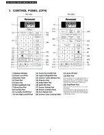
Page 6: ...3 CONTROL PANEL CPH 6 NN S262SF NN S262BF NN S262WF NN S252BF NN S252WF ...
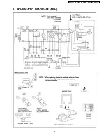
Page 9: ...5 SCHEMATIC DIAGRAM APH 9 NN S262SF NN S262BF NN S262WF NN S252BF NN S252WF ...
Page 10: ...6 SCHEMATIC DIAGRAM CPH 10 NN S262SF NN S262BF NN S262WF NN S252BF NN S252WF ...
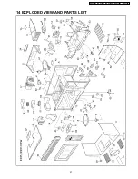
Page 27: ...14 EXPLODED VIEW AND PARTS LIST 27 NN S262SF NN S262BF NN S262WF NN S252BF NN S252WF ...
Page 34: ...34 NN S262SF NN S262BF NN S262WF NN S252BF NN S252WF ...

