background image

73

72

Communication

Transmission sequence
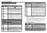
• Handshake code

For line control, following codes are used:

Name Code

Functions

Description

SOH 01h Heading start

Start code of communication data, which is followed by address.

STX 02h Text start

Start code for sending command data.

ETX 03h Text end

Termination code for command data.

EOT 04h Transmission end

Sent from the amplifier when transmission message is finished.

ENQ 05h Request for 

sending

Inquiry code from host controller to amplifier. The amplifier sends 

data transmission command when sending data is available, and 

transmission end command when sending data is not available.

ACK 06h Positive response

Sent when received message is judged to be normal.

NAK 15h Negative response Sent when received message is judged to be abnormal.

• The protocol is compatible with the basic mode data transmission control procedure JISX5002.

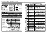
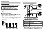
• Composition of sent and received data

Shows composition of data transferred on physical phase. 

There are two transmission patterns available depending on the contents of command.

Sending address:  Set the mating device number for sending data in ASCII2 byte.


Host ID 01h (01) to 1Fh (31)


Amplifier ID 80h (128) to 9Fh (159)


When the sending address is set to 80h (128), all connected ampli-

fiers executes the command (only for some commands). However, 

response is not made from the amplifier

Request for sending/ Positive response/

Negative response/ Transmission end command

(Host

Amplifier, Amplifier

Host)

Data transmission command

(Host

Amplifier, Amplifier

Host)

<NOTE>

One block in the table represents 

1 byte (character).

SOH

Sending address 1

Sending address 2

Senders address 1

Senders address 2

ENQ/ACK/NAK/EOT

SOH

Sending address 1

Sending address 2

Senders address 1

Senders address 2

STX

Command 1

Command 2

Data number 1

Data number 2

Data number 3

Data number 4

Data 1

Data 2

Data 3

Data 4

ETX

BCC

Senders address: Set the address of communication sending source (self) in ASCII 2 

bytes. 


Host ID 01h (01) to 1Fh (31)


Amplifier ID 81h (129) to 9Fh (159)

Command:  

Control command (2 bytes)

Data number:  

Set the data number to be controlled in ASCII 4 bytes.

Data:  

Set the writing data in ASCII 4 bytes.


When data is minus, it is converted by signed 16 bits.


(e.g. In the case of –10, data is ASCII code of hexadecimal FFF6.)

BCC: 

In the case of data transmission command, set XOR (logically invert-

ed) value of each byte from STX to ETX.
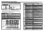
• List of commands

Command

Code

Transmission

direction

Description

$P

24h 50h Host

Amplifier

Data writing command. Change of parameter and motor 

control data. (In changing parameter, parameter is not 

written to EEPROM.)

$S

24h 53h Host

Amplifier

Data writing command. Change of parameter and motor 

control data. (In changing parameter, parameter is 

written to EEPROM.) 

* Writing to EEPROM should be requisite minimum.  

  (EEPROM endurance: approx. 100,000 write cycle.)

$R

24h 52h Host

Amplifier

Data reading request command. Command which 

requests the parameter, status, and control detail of 

amplifier.

#R

23h 52h Amplifier

Host

Response to data reading request. Returns the 

parameter, status, and control detail of amplifier to $R.

#C

23h 43h Amplifier

Host

Data update request response. Returns the status of 

amplifier (8103h) to host in response to request for 

sending command when data of amplifier status (8103h) 

has changed from previous request for sending.

#

I

23h 49h Amplifier

Host

Initial request response. When the amplifier is powered 

on, 9999 is sent following #

I

 in response to initial inquiry 

from host controller (Request for sending).

Summary of Contents for MINAS-BL GP series

Page 1: ...onfiguration and wiring 12 Wiring 14 How to use Digital key pad option 18 Test run 26 Checking load and use condition 28 Assembling of gear head 30 Maintenance inspections 31 Protective functions 32 P...

Page 2: ...An over current protection earth leakage breaker over temperature protecter and emergency stop device must be installed The failure could result in electric shocks injuries or fire Do not subject the...

Page 3: ...ult in fire Ambient temperature of installed motor and amplifier should be under permittable one The failure could result in damages This product should be treated as an industrial waste when it is di...

Page 4: ...nication Output 5A 50 W 9A 90 W 1E 130 W Compact geared motor drive Introduction Checking the model After unpacking Make sure that the model is what you have ordered Check whether the product has been...

Page 5: ...otor is not subjected to rain water and direct sun beam 2 Do not use the motor in corrosive atmosphere such as hydrogen sulfide sulfurous acid chlorine ammonia sulfur gas chloride gas sulfide acid alk...

Page 6: ...oil or water Stress to cable 1 Make sure that stress is not applied to the lead or connection of cable due to bending or dead weight 2 In installation where the motor moves fix the cable of motor and...

Page 7: ...se 100 200 V DV0P4170 SUP EK5 ER 6 OKAYA ELECTRIC IND CO LTD 3 phase DV0PM20042 3SUP HU10 ER 6 Selection of Molded Case Circuit Breaker MCCB magnetic contactor and electric wire wiring within equipmen...

Page 8: ...8 N m External regenerative resistor Power supply input L1 L2 1 5 6 10 MCCB Molded Case Circuit Breaker Grounding Noise filter External regenerative resistor Forced trip 02 Connector for control signa...

Page 9: ...Digital key pad 3 SOT Interface for Digital key pad or PANATERM for BL 4 SIN 5 RS485 For connect RS485 6 RS485 For connest RS485 7 GND Power supply GNG for Digital key pad 8 SCK Interface for Digital...

Page 10: ...ction CCW rotation when viewed from motor output shaft default Switch When switch is pressed the setting change warning CAU is displayed and the motor is stopped and tripped Switch In monitor mode Whe...

Page 11: ...flashing Control changes to this mode when switch is pressed in parameter number mode Parameter number can be changed and selected by and switch Parameter setting mode Displays the detail of paramete...

Page 12: ...power is turned on and when monitor mode display is on See P 45 for setting of Pr7A Teaching function This motor allows two target position setting methods one of which is setting by param eter value...

Page 13: ...y again Copy error This error occurs in the attempt to copy data between products with different function Press switch to cancel the error Although parameters can be copied between the same models wit...

Page 14: ...up All light up All light up All light up Flashing Flashing Flashing Description of operation Operation panel Switch LED display Inspection before Test run 1 Make sure that all wiring is correct 2 Mak...

Page 15: ...nt medium impact 2 5 3 0 3 5 Permissible torque The required gear head allowable shaft torque TA can be determined based on the service factor and actual load torque T1 TA T1 Sf Select a gear head mot...

Page 16: ...inion faced up Outward direction of motor leadwire can be aligned with any one of 4 sides of gear head with an output shaft at a different position Faucet portion end face Output shaft Faucet face O r...

Page 17: ...ist of protective functions Display on the Digital key pad Trip number RS485 Protective function Causes Countermeasure 2 Undervoltage error E LV The motor trips when internal DC voltage voltage of smo...

Page 18: ...etting of sensor is abnormal Investigate the setting of parameter home sensor and wiring of home sensor 22 Present position overflow error E OF The motor trips after homing is completed if present pos...

Page 19: ...ation or noise Output shaft of motor gear head and shaft of load are not aligned Check the connection between the output shaft of motor gear head and the load Motor and gear head are not assembled cor...

Page 20: ...000 2000 You can set the speed moving to the 2nd point Setting unit r min Parameter No Pr Name of parameter Effective after power resetting Setting range Default Description 0C The 2nd point The 2nd a...

Page 21: ...forward add position command to speed command When the setting is increased the position error is decreased and response improved which makes overshoot large Setting unit Parameter No Pr Name of para...

Page 22: ...e detection value 50 to 150 50 You can limit the output torque of motor when returning to bumping home You can set it in with reference to the rated torque Parameter No Pr Name of parameter Effective...

Page 23: ...utput is normal logic output transistor is off in tripping and output transis tor is on in no tripping 5F 02 output polarity selection 0 1 0 60 RS485 device number 128 to 159 129 See P 70 61 RS485 com...

Page 24: ...hen 1 rotations and 144 pulses are set at the target position the travel distance is 432 pulses this represents a travel distance of 1 5 rotations Negative values can also be set on the pulse value Wh...

Page 25: ...allows continuous positioning to more than one point by single operation in struction continuous block operation or changing the speed setting on the way of opera tion combined block operation when bl...

Page 26: ...point or the 4th point and the motor runs to the target position e g When the 1st point and the 2nd point are set to combined block operation Pr06 2 Commanded speed 1 When the 1st speed setting the 2n...

Page 27: ...ration In applications where homing operation is not required set Pr48 at 1 then the position where power is turned on is assumed to be the home 0 by which positioning operation is enabled After compl...

Page 28: ...or direction limit sensor Starting point Home Home Starting point Offset Offset Coordinate system Homing direction In using this mode the motor at the home position is within the limit sensor therefor...

Page 29: ...ff the motor does not run in direction Limit function is disabled when this signal is not used Function number Assignment function Description of function 13 Limit in direction Make wiring so that the...

Page 30: ...detection filter 2C 34 Sets the time constant of low pass filter of speed feedback Velocity feed forward time constant 2d Filter in velocity feed forward Torque limit 2E 35 Limits the output torque of...

Page 31: ...irection 42 Homing speed 200 Set any desired operation speed 44 Homing acceleration deceleration time 200 Set any desired acceleration deceleration time 48 Homing function 2 Set to 1 when setting powe...

Page 32: ...arameter marked with is effective after power resetting Function Parameter No Pr Name of parameter Setting Remarks Selection of signal function 50 I1 function selection 9 Sequential run start 51 I2 fu...

Page 33: ...g acceleration deceleration time 200 Set any desired acceleration deceleration time 48 Homing function 2 Homing operation by initial I1 input when power is turned on 49 Selecting homing when motor is...

Page 34: ...election of signal function 50 I1 function selection 8 Run start 51 I2 function selection 6 Point designation 1 input choosing the 1st 2nd point 52 I3 function selection 15 Motor free input 53 I4 func...

Page 35: ...ommunication software PANATERM for BL Can be download ed from our web site Example of connection RS485 Host controller Device number 01h 1 Device number 81h 129 Device number 82h 130 Brushless amplifi...

Page 36: ...nse time is the short est time for setting transmission mode in RS485 bus for response after the amplifier has received communication data Actual data response time depends on the type and data of ord...

Page 37: ...rs address 2 ENQ ACK NAK EOT SOH Sending address 1 Sending address 2 Senders address 1 Senders address 2 STX Command 1 Command 2 Data number 1 Data number 2 Data number 3 Data number 4 Data 1 Data 2 D...

Page 38: ...0000 as reading data parameter address is answered Check whether the data No parameter address is correct then use the reading data 5 Host Amplifier Result response SOH ACK Amplifier ID Host ID 6 Amp...

Page 39: ...communication When power is turned on Communication data is shown below in chronological order when request for sending is executed in power on for the amplifier Initial request response at the first...

Page 40: ...al ASCII code SOH 01h 8 38h 1 31h 0 30h 1 31h STX 02h 24h P 50h 8 38h 0 30h 0 30h 0 30h 0 30h 0 30h 0 30h SOH 01h 0 30h 1 31h 8 38h 1 31h ACK 06h A 41h ETX 03h BCC 0Ch Host Amplifier Host Amplifier Co...

Page 41: ...ier Host Communication Communication command Data number Applicable command on host side Description 8000h to 807Fh P S R Parameter 8103h R Amplifier status 8104h R Model code 1 8105h R Model code 2 8...

Page 42: ...quested parameter address is abnormal 0000 as parameter value is answered You should check parameter address as you requested When the parameter reading request command is normally completed the ampli...

Page 43: ...30 0 8104h Model code 1 8105h Model code 2 R Model code reading request command Received data Host Amplifier SOH STX R 8 1 0 0 0 0 0 ETX BCC Amplifier ID Host ID Command Data number Data value Enter r...

Page 44: ...first it is possible that wrong target position information before updating may be read out so be sure to follow the reading order 8117h rotation number 8118h pulse Use for only monitoring function Co...

Page 45: ...mand cannot be given through I O See I1 I2 function selection on P 44 When Pr3E is 0 command through I O run command by this command is ignored When run command is given to the amplifier with this com...

Page 46: ...ific functions and directly sold to general consumers in EU countries These products are required to meet the EU unified standards and to be furnished with CE marking Our brushless motor meet the EC D...

Page 47: ...ge absorber may be ruptured Grounding Be sure to connect the grounding Terminal of brushless amplifier and protective grounding wire PE of system for preventing electric shock Do not tighten the groun...

Page 48: ...mm from the shaft end Bearing Ball bearing Insulation resistance Measure the insulation resistance with 500 V Megger It must be above 20 M Measuring position Between power input line L1 L2 L3 and grou...

Page 49: ...Max 31 units Change parameter Monitor of condition Parameter change status monitor etc can be executed through a store bought PC Communication software PANATERM for BL Digital key pad connection cable...

Page 50: ...region 4000 3000 2000 1000 0 5 0 25 0 35 0 22 0 90 W 100V 90 W 200V 130 W 100V Torque N m 4000 3000 2500 2000 1000 0 8 0 4 0 62 0 62 0 41 0 31 0 24 0 130 W 200V Torque N m Rotation speed r min Rotati...

Page 51: ...12 2 Hexagon socket head bolt Key See key dimension 1 MB9G BV Reduction gear ratio in Reduction gear ratio is available in 6 types 5 10 15 20 30 and 50 Key dimension 6 25 0 0 030 6 0 0 030 For 90W 13...

Page 52: ...ire of the extension cable to the earth terminal of the brushless amplifier For connecting grounding wire of motor and motor extension cable use M4 screw and insulating cap supplied as accessories Ins...

Page 53: ...cable Cable with an I O connector Optional parts number DV0PM20076 Length L 2 m 39 01 2105 5557 10R 210 6 1 7 2 8 3 9 4 10 5 2000 200 30 10 5 20 5 20 5 20 5 Cable AWG26 10 wire type BANDO DENSEN Co lt...

Page 54: ...attachment unit Optional parts number DV0P3811 130 5 5 140 7 20 35 2 M4 bar ring for mounting Mounting plate Rail stopper 6 6 Unit mm Part where DIN rail is mounted DIN rail With rail stop pushed in...

Page 55: ...us accident or loss of property is expected due to the failure of this product If you are planning to use this product under special environment such as atomic power control aerospace equipment traffi...

Page 56: ...e downloaded from the following web site http industrial panasonic com ww i_e 25000 motor_fa_e motor_fa_e html Pursuant to at the directive 2004 108 EC article 9 2 Panasonic Testing Centre Panasonic M...

Reviews: