


−
B27
−
−
B26
−
English
3. System Configuration and Wiring
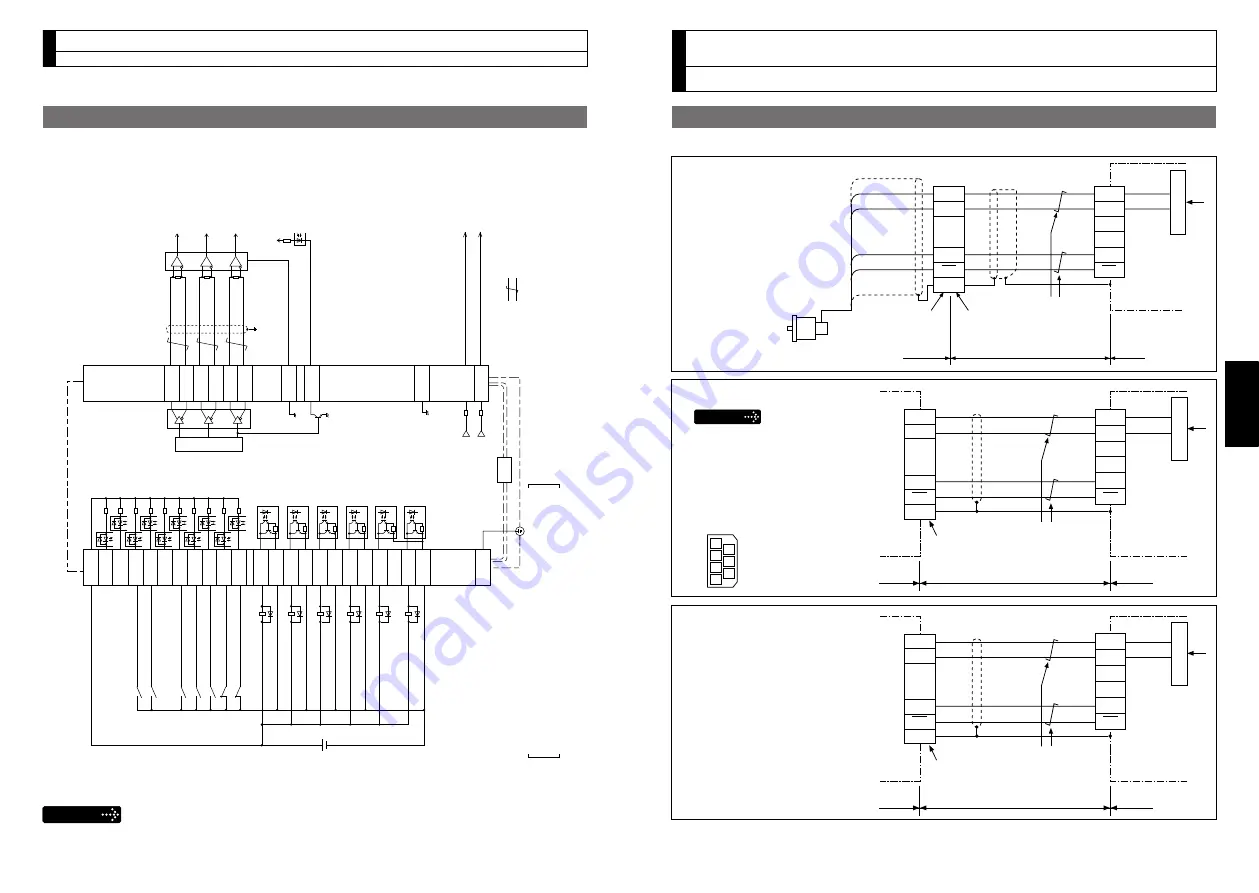
Wiring to the connector, X6
Connection to Encoder
• In case of 20-bit incremental encoder
MSMD 50 W to 750 W
MHMD 200 W to 750 W
MSME 1.0 kW to 5.0 kW
MDME 1.0 kW to 5.0 kW
MFME 1.5 kW to 4.5 kW
MGME 900 W to 4.5 kW
MHME 1.0 kW to 5.0 kW
Shell (FG)
+5 V
0 V
1
2
3
4
5
6
4
1
3
7
Twisted pair
Encoder cable
Connector: JN2DS10SL1-R
(by Japan Aviation Electronics Ind.)
Motor
Driver
E5V
E0V
PS
PS
9
PS
PS
FG
E5V
E0V
X6
Regulator
X6
Shell (FG)
Motor
1
2
3
4
5
6
4
5
2
3
6
E5V
E0V
E5V
E0V
PS
PS
FG
PS
PS
Driver
Motor
+5 V
0 V
Junction cable
172160-1
(by Tyco Electronics, AMP)
172168-1
(by Tyco Electronics, AMP)
White
Twisted pair
Black
Purple
Light blue
Regulator
Shell (FG)
+5 V
0 V
1
2
3
4
5
6
6
3
7
4
Twisted pair
Encoder cable
Connector: JN6FR07SM1
(by Japan Aviation Electronics Ind.)
Motor
Driver
E5V
E0V
PS
PS
1
PS
PS
FG
E5V
E0V
X6
Regulator
MSME 50 W to 750 W
Tighten the motor connector
mounting screw (M2) with a torque
between 0.19 and 0.21 N
•
m.
To avoid damage, be sure to use
only the screw supplied with the
connector.
[Connector pin assignment]
(Viewed from cable)
2 5
1
3 6
4 7
Caution
Wiring Example of Internal Velocity Control Mode
3. System Configuration and Wiring
Wiring to the connector, X4
SP
IM
1 k
Ω
1 k
Ω
FG
50
43
42
X4
( represents twisted pair
.)
A-phase output
B-phase output
Z-phase output
Velocity monitor output
Torque monitor output
7
COM+
INH
CL
SR
V-ON
GAIN
DIV1
ZEROSPD
C-MODE
A-CLR
POT
NOT
S-RDY+
S-RDY
-
ALM+
AT
-SPEED
+
BRKOFF
+
BRKOFF
-
TLC
V
DC
12 to 24 V
ZSP
COM
-
AT
-SPEED
-
ALM
-
33
30
29
27
28
26
32
31
9
8
35
34
37
36
39
38
11
10
40
12
41
Servo-ON input
Gain switching input
Alarm clear input
Servo-Ready output
Servo-Alarm output
At-speed output
External brake release output
Torque in-limit output
Zero speed detection output
Speed zero clamp input
Control mode switching input
Positive direction over-travel inhibition input Negative direction over-travel inhibition input
4.7 k
Ω
OA+
OA
-
OB+
OB
-
OZ+
OZ
-
GND
CZ
21
22
48
24
25
19
49
23
Z-phase output (open collector)
GND
17
The functions of the following pin can be changed using parameters. Input: 8, 9, 26, 27, 28, 29, 30, 31, 32, 33 Output: 10-11, 12, 34-35, 36-37, 38-39, 40
Remarks
X1 to X7 are used for the secondary circuit. To connect these terminals to the primary
power supply (particularly, the 24 VDC power supply for brake), insulation is required.
Do not connect these terminals to the same power supply.
* For connection of IP65 motor, refer to the Operating Instructions (Overall).