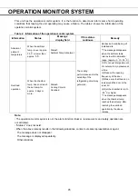
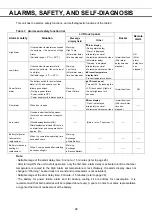
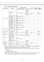
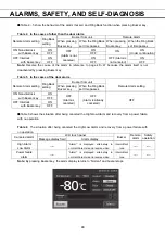
background image


44


OTHER PARAMETERS


Each setting 

Brightness(Active):  

Brightness of LCD touch panel of the usual state. Adjust Brightness(Active) slide bar or input set value 
into the Brightness(Active) input box. Settable range: 50

80, factory setting: 80. 


Sleep:  

The function is that the rightness of LCD touch panel is lowered to save electricity, when there is no key 
operation during set time. 
By holding the Sleep slide key and sliding it right, the Sleep function is turned to ON. Input the set value 
of time to change the Sleep state. Settable range: 1 minute

5 minutes, factory setting: 2 minutes. 

Note:

 It is not possible to operate any key in the Sleep state. By touching the LCD touch panel, the Sleep 

state is released and the LCD touch panel returns to the usual state. Under this condition, key operations 
are available. 
 

Brightness(Sleep):  

Brightness of LCD touch panel of the Sleep state. Adjust Brightness(Sleep) slide bar or input set value 
into the Brightness(Sleep) input box. Settable range: 0

50, factory setting: 20. 


5.

 Press Top key to return to the Top screen.


Summary of Contents for MDF-DC500VX Series

Page 1: ...carefully before using this product and save the operating instructions for future use See page 61 for all model numbers MDF DC500VX MDF DC700VX Series Operating Instructions MDF DC500VX MDF DC700VX Ultra Low Temperature Freezer MDF DC700VX ...

Page 2: ... mode P 22 Setting key lock P 24 Removing key lock P 26 ALARM PARAMETERS P 27 OPERATION ALARM LOG Setting log interval P 30 Displaying operation log P 31 Exporting operation log P 34 Displaying alarm log P 37 Exporting alarm log P 39 OTHER PARAMETERS Setting date and time P 42 Setting brightness and sleep P 43 OPERATION MONITOR SYSTEM P 45 ALARMS SAFETY AND SELF DIAGNOSIS P 46 ROUTINE MAINTENANCE ...

Page 3: ...uctions will be subjected to change without notice due to the improvement of performance or functions Contact our sales representative or agent if any page of the operating instructions is lost or page order is incorrect Contact our sales representative or agent if any point in the operating instructions is unclear or if there are any inaccuracies No part of the operating instructions may be repro...

Page 4: ...ailure to observe CAUTION signs could result in injury to personnel and damage to the unit and associated property Symbol shows This symbol means caution This symbol means an action is prohibited This symbol means an instruction must be followed Be sure to keep the operating instructions in a place accessible to users of this unit NOTE As with any equipment that uses CO2 gas there is a likelihood ...

Page 5: ...ower supply outlet is not grounded it will be necessary to install a ground by qualified engineers Never ground the unit through a gas pipe water main telephone line or lightning rod Such grounding may cause electric shock in the case of an incomplete circuit Connect the unit to a power source as indicated on the rating label attached to the unit Use of any other voltage or frequency other than th...

Page 6: ...ure to disconnect the power supply plug may cause fire if there is something wrong with the unit When removing the plug from the power supply outlet grip the power supply plug not the cord Pulling the cord may result in electric shock or fire by short circuit Disconnect the power supply plug before moving the unit Take care not to damage the power cord A damaged cord may cause electric shock or fi...

Page 7: ... as acid or alkali in this unit if the container cannot be sealed These may cause corrosion of inner components or electric parts Check the setting when starting up of operation after power failure or turning off of power switch The stored items may be damaged due to the change of setting Be careful not to tip over the unit during movement to prevent damage or injury Prepare a safety check sheet c...

Page 8: ...ing circuit Warning fire Personal injury Frostbite and frost Interior Frostbite and frost caution label SYMBOLS ON UNIT The symbols are attached to the ultra low temperature freezer The following table describes the symbols This symbol is attached to covers that access high voltage electrical components to prevent electric shock Only a qualified engineer or service personnel should be allowed to o...

Page 9: ...of OVERVOLTAGE CATEGORY II Temporary OVERVOLTAGES occurring on the mains supply Applicable pollution degree of the intended environment POLUTION DEGREE 2 in most cases INTENDED USE AND PRECAUTIONS This equipment is designed for low temperature storage of human cells organs plasma and DNAs The effective storage period depends on the sample condition and storage temperature It is necessary to determ...

Page 10: ...he model below is the MDF DC700VX However the MDF DC500VX is also equivalent structures 11 12 13 1 3 2 Caster 6 pieces 8 3 pieces on the front side 9 4 3 pieces Back side Handle Side table 7 6 5 10 Right side 14 15 16 17 18 19 20 ...

Page 11: ...from a liquid CO2 cylinder refer to page 59 12 Access port This is used for leading a cable and sensor of a measuring equipment to chamber Note Re install the access port cap and the insulating pad after use Incomplete installation may cause poor cooling or dew condensation outside the access port 13 Fixture 2 fixtures are provided as spacers between the cabinet and wall and also serve as hooks to...

Page 12: ...2 for details 4 Control display The present operation control mode is displayed refer to page 22 23 for setting Normal control Normal is displayed Eco control ECO is displayed 5 Alarm display Refer to page 46 47 for details of alarms Normal condition Normal is displayed Alarm activated buzzer delayed Alarm is displayed alternately in normal characters and reverse video Alarm activated buzzer sound...

Page 13: ...arm errors or information of the operation monitor system the message on the screen is changeable 10 Menu key Press this key to lead the Menu screen It is possible to set various setting on the Menu screen Refer to page 18 11 Buzzer key Press this key to silence the buzzer However when the ring back is ON the buzzer will sound again when the ring back passed and the alarm state still continues Ref...

Page 14: ... In the door alarm the remote alarm does not work Refer to page 46 Table 1 The behavior of the remote alarm when pressing Buzzer key Remote Alarm setting Refer to page 27 29 Connecting terminal Normal condition Abnormal condition Including in the cases of power outage and of where the power plug is pulled out When pressing Buzzer key ON Non interlock with Buzzer key COM N C Close Open Open Maintai...

Page 15: ...ll the unit in stable condition to avoid the vibration or noise Unstable condition may cause vibration or noise WARNING Install the unit on a sturdy floor If the floor is not strong enough or the installation site is not adequate this may result in injury from the unit falling or tipping over Select a level and sturdy floor for installation This precaution will prevent the unit from tipping Improp...

Page 16: ...ls with a dry cloth Note Remove the cable tie banding the power supply cord Prolonged banding may cause the corrosion of the cord coating 2 Adjust the leveling feet It is possible to adjust the length of the leveling feet by turning them Fig 1 Lengthen the leveling feet until the casters are lifted from the floor and let 3 leveling feet support the front side of this unit After that adjust 3 level...

Page 17: ...he alarm test Make sure that the buzzer sounds by pressing Buzzer key for 5 seconds Press Buzzer key again to stop the buzzer and the alarm test finishes 9 When an optional backup cooling kit MDF UB5 is installed After the chamber temperature reaches the set temperature turn ON the backup power switch Note When operating this unit for the first time or after not using it for an extended period of ...

Page 18: ...ion log data and alarm log data during a power failure is saved Note When the capacity of the battery for power failure alarm is flat during a power failure subsequent operation log data and alarm log data is not saved Operation after recovery from power failure The set value is memorized by nonvolatile memory Accordingly the chamber resumes the operation with setting before power failure Note It ...

Page 19: ...h can be exported 31 33 Data Export Export screen Actual Temp Export Chamber temperature log 34 36 Door Opening Export Door opening log 34 36 Setting Setting Log interval Unique ID 30 31 Alarm Display Alarm log can be exported 37 38 Alarm Export Export Alarm log 39 41 Key Lock Key Lock screen Setting Key lock ON OFF password 24 26 Tools Tools screen Operation Setting Setting Eco operation ON OFF c...

Page 20: ...dow is displayed 2 Press Numeric key or Up Down key to input numerical value and press OK key Key description Numeric key 0 9 Input numerical value Up Down key Increases or decreases the numerical value displayed in the numeric input box Clear key Deletes the numerical value displayed on the numeric input box Cancel key Stops inputting on the numeric input box and closes the input window Note Up D...

Page 21: ...etic characters or spaces Numeric key 0 9 Input numerical values UC LC key A a Change UC LC of alphabetic key Left Right key Move the cursor to left right Delete key Delete an alphanumeric character on the right side of the cursor Cancel key Stops inputting on the alphanumeric input box and closes the alphanumeric input window Note While the alphanumeric input window is open it is not possible to ...

Page 22: ...ay returns to the Menu screen Each parameter setting Temperature Set value of chamber temperature Settable range 50 o C 90 o C Control range 50 o C 86 o C factory setting 80 o C High Alarm When the chamber temperature exceeds the High Alarm set temperature the set temperature the set value of High Alarm the High Alarm is activated Settable range 5 o C 40 o C factory setting 10 o C Low Alarm When t...

Page 23: ...hen the value of the current chamber temperature is equal to the High Low Alarm set temperature 4 On the Menu screen press Back key to return to the Top screen Setting operation control mode 1 Press Menu key to lead the Menu screen 2 Press Tools key to lead the Tools screen 3 Press Operation Setting key to lead the Operation Setting screen ...

Page 24: ...m turning ON this unit until starting its compressor This unit is required a large electric power at the moment its compressor starts When some units are in a same room set so as to be shifted to each other the compressor delay times to prevent the simultaneous start of all compressors after power failure Settable range 3 minutes 15 minutes factory setting 3 minutes Note This unit has two compress...

Page 25: ...ad the Menu screen 2 Press Key Lock key to lead the Key Lock screen 3 On the Key Lock screen it is possible to set each setting of key lock refer to next page Press Apply key to change key lock ON and to save the password The display returns to the Menu screen ...

Page 26: ...nput box When inputting different password Notice dialog box is displayed Press OK key and input the correct password Note Manage the release password of Key Lock properly 4 On the Menu screen press Back key to return to the Top screen Operation for Keylock ON When pressing Menu key Password input box is displayed and input of the release password of Key Lock is required When the inputted password...

Page 27: ... press OK key to lead the Menu screen 3 Press Key Lock key to lead the Key Lock screen 4 On the Key Lock screen by holding Key Lock slide key and sliding to the left change to OFF Press Apply key to turn the key lock OFF The display returns to the Menu screen Note The release password of key Lock is deleted 5 On the Menu screen press Back key to return to the Top screen ...

Page 28: ...27 ALARM PARAMETERS 1 Press Menu key to lead the Menu screen 2 Press Tools key to lead the Tools screen 3 Press Alarm Setting key to lead the Alarm Setting screen ...

Page 29: ... 2 minutes Note When the unit is recovered from the alarm state within the door alarm delay time the buzzer does not sound after the elapse of the door alarm delay Ring Back The function is that the alarm buzzer sounds again when the alarm state still continues after the alarm delay set time passed even though the alarm buzzer was stopped by pressing Buzzer key By holding and sliding Ring Back sli...

Page 30: ...nced by pressing Buzzer key For the behavior at the time of pressing Buzzer key and the re activation of alarm under each setting condition refer to Table 4 5 on page 48 Resolve the cause of the alarm in reference to page 46 47 because the alarm itself is not deactivated by pressing Buzzer key except for some alarms ...

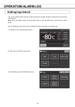
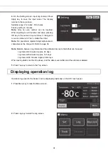
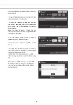
Page 31: ...lose state of door Note When the battery switch for power failure alarm is ON operation log is saved during a power failure Use the following procedure to set the log interval interval of acquiring the operation log 1 Press Menu key to lead the Menu screen 2 Press Log key to lead the Log screen 3 Press Setting key to lead the Setting screen ...

Page 32: ...r 8 digit alphanumeric characters as the Unique ID Refer to page 36 Note Relation between log interval and the estimated amount of data that can be saved Log interval 2 minutes Approx 46 days Log interval 6 minutes Approx 135 days Log interval 30 minutes Approx 664 days When saving data more than the above and the data is overwritten and the old data is delated 5 Press Top key to return to the Top...

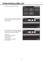
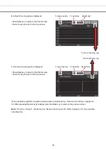
Page 33: ...f the operation log you want to display graphically 5 On the Chart screen by pressing Show key after pressing the item you want to display graphically the graph of each operation log is displayed Actual Temp Chamber temperature log graph Go to procedure 6 Door Opening Open close state of door log graph Go to procedure 7 ...

Page 34: ...o the Top screen When exporting operation log data without pressing the Export key follow the procedure on page 34 36 When pressing Export key by mistake press the Back key to return to the previous screen Note The error of about 1 minute may be observed during a month Refer to page 42 for the procedure of setting time To previous day To next day To Door Opening log To Actual Temp log To previous ...

Page 35: ... to the USB memory inserted into the USB port 1 Insert the USB memory into the USB port Note It is not possible to use a USB memory with security functions that requires entering password 2 Press Menu key to lead the Menu screen 3 Press Log key to lead the Log screen 4 Press Data Export key to lead the Export screen ...

Page 36: ... a month Refer to page 42 for the procedure of setting time 6 On the Export screen select the type of operation log data you want to export To export all types of operation log data press All Ch key To export only operation log data you want to export select operation log data you want to export and then press Selected Ch key Actual Temp Chamber temperature log data Door Opening Open close state o...

Page 37: ... USB memory and the exported file is saved in it in CSV format The exported file name is in date 8 digits type of data format e g When exporting all types of data using All from Oct 1st 2015 to Jan 1st 2016 20151001 20160101_AllCh csv 20151001 20160101_Door csv e g When exporting Actual Temp using 1 Day Jan 1st 2016 20160101_Temp csv On the beginning of the exported file product name MDF DC500VX o...

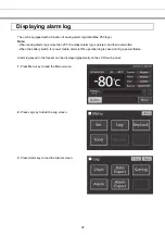
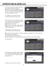
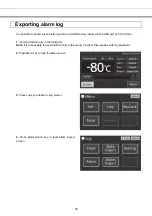
Page 38: ...st alarm log is deleted and then overwritten When the battery switch for power failure alarm is ON operation log is saved during a power failure Alarm log saved in the freezer can be displayed graphically on the LCD touch panel 1 Press Menu key to lead the Menu screen 2 Press Log key to lead the Log screen 3 Press Alarm key to lead the Alarm screen ...

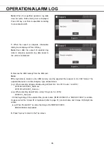
Page 39: ...ge 1 day 45 days Note The error of about 1 minute may be observed during 1 month Refer to page 42 for the procedure of setting time Press Back key to return to the Log screen Press Top key to return to the Top screen On the Alarm screen of procedure 4 or 5 alarm log data can be exported in CSV format to the USB memory inserted into the USB port 6 Insert the USB memory into the USB port Note It is ...

Page 40: ... the USB port by CSV format 1 Insert a USB memory in the USB port Note It is not possible to use a USB memory with security functions that requires entering password 2 Press Menu key to lead the Menu screen 3 Press Log key to lead the Log screen 4 Press Alarm Export key to lead Alarm Export screen ...

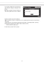
Page 41: ... button and input days Settable range 1 day 45 days Note The error of about 1 minute may be observed during 1 month Refer to page 42 for the procedure of setting time 6 Press Export key Note When USB memory is not inserted in the USB port Notice dialog box is displayed Press OK key and insert an USB memory into the USB port When alarm log data does not exist in the specified days Notice dialog box...

Page 42: ...eted 8 Remove a USB memory from the USB port Note A log folder is created in a USB memory and an exported data file is saved in the log folder by CSV format Exported file name The first date during exported period 8 digits the last date 8 digits AlarmLog Example When exporting alarm log data for 7 days on January 7 2016 20160101 20160107_AlarmLog csv 9 Press Top key to return to the Top screen ...

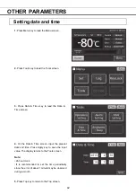
Page 43: ...key to lead the Date Time screen 4 On the Date Time screen input the present date and time Press Apply key to save the input value The display returns to the Tools screen Note 24 hour clock It is recommended to set the time periodically since the error of about 1 minute may be observed during a month 5 Press Top key to return to the Top screen ...

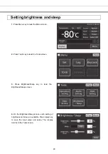
Page 44: ...ress Tools key to lead the Tools screen 3 Press Brightness Sleep key to lead the Brightness Sleep screen 4 On the Brightness Sleep screen each setting of brightness and sleep is available Press Apply key to save the input value and setup The display returns to the Tools screen ...

Page 45: ... right the Sleep function is turned to ON Input the set value of time to change the Sleep state Settable range 1 minute 5 minutes factory setting 2 minutes Note It is not possible to operate any key in the Sleep state By touching the LCD touch panel the Sleep state is released and the LCD touch panel returns to the usual state Under this condition key operations are available Brightness Sleep Brig...

Page 46: ...en the ambient temp returns to within allowable range approx 0 o C 35 o C Overload operation When the chamber temp does not reach the set temp for approx 5 days or more Status3 Cooling Circuits Overload 1 Do not put a large amount of contents to cryopreserve at a time 2 Reduce the opening frequency of the door 3 Make sure that there is no leak around the door or the inner lid 4 Set the chamber tem...

Page 47: ...ghts in the set brightness for 5 seconds Intermittent tone ON Door alarm When door is open Door display Open is displayed alternately in normal characters and reverse video Intermittent tone After door delay time has elapsed Auto return On screens other than the Top screen there is no key operation for approx 90 s When the sleep function is ON After sleep functionis turned ON there is no alarm err...

Page 48: ...her Err20 Condenser A Temp Abnormal Warning is displayed alternately in normal characters and reverse video Intermittent tone ON Compressor A OFF Condenser B temp abnormality If the temperature of the condenser sensor B is 50 o C or higher Err21 Condenser B Temp Abnormal Compressor B OFF Communication error When communication between LCD touch panel and control substrate is died out or unstable Er...

Page 49: ...alarm Remote Alarm setting Ring Back setting Buzzer from unit Remote Alarm setting When pressing Buzzer key When the Ring Back set time passes ON Non interlock with Buzzer key ON OFF Alarm is canceled OFF Alarm is already canceled OFF OFF OFF Interlock with Buzzer key ON OFF Table 6 shows the situation after being canceled the High Low Alarm and recovery from a power failure with no operation Tabl...

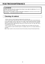
Page 50: ...of the unit and all accessories If the outside panels are dirty clean them with a diluted neutral dishwashing detergent Undiluted detergent can damage the plastic components For the dilution refer to the instruction of the detergent After the cleaning with the diluted detergent always wipe it off with a wet cloth Then wipe off the cabinet or accessories with a dry cloth Never pour water onto or in...

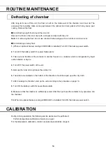
Page 51: ...ake out and transfer all the contents to another freezer or a container which is refrigerated by liquid carbon dioxide or dry ice 4 Turn OFF the power switch of the unit 5 Remove the inner lids and leave the unit as it is 6 The water accumulated on the bottom of the chamber should be wiped up with a dry cloth 7 After cleaning the chamber start up the unit according to the procedure on page 16 8 Tu...

Page 52: ...he used battery is a recyclable precious resource Do not dispose of the battery Always follow the procedure for recycling Replacing the battery for backup cooling kit Replace the battery for backup cooling kit every 3 years Contact our sales representative or agent for the replacement of battery when Warning Exchange a Backup Battery is displayed in the message display field The replacement of the...

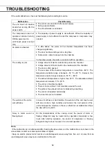
Page 53: ...wever the temperature control range is between 50 o C 86 o C The ambient temperature is higher than 30 o C The allowable ambient temperature is between 5 o C 30 o C The unit is in the direct sunlight There is no more than 10 cm clearance around the unit The grille or the exhaust air bent is blocked by something The unit is not installed horizontally The inner lids are not installed The outside of ...

Page 54: ...tored unused in an unsupervised area for an extended period ensure that children do not have access and doors cannot be closed completely The disposal of the unit should be accomplished by appropriate personnel Always remove doors to prevent accidents such as suffocation Recycle of battery Label indication is obliged to comply with Japanese battery regulation ...

Page 55: ...spose of them correctly at your local community waste collection recycling centre Please help us to conserve the environment we live in German Für EU Staaten Das Symbol und das erwähnte Wiederverwertungssystem gelten nur für die Länder der EU und nicht für andere Länder oder Gebiete in der Welt Die Produkte von Panasonic werden aus hochwertigen Materialien und Komponenten gefertigt die sich wieder...

Page 56: ...ées de manière inappropriée peuvent s avérer potentiellement dangereuses pour la santé humaine et pour l environnement Cependant ces matières sont nécessaires au bon fonctionnement de votre appareil ou de votre machine Pour cette raison il vous est demandé de ne pas vous débarrasser de votre appareil ou machine usagé avec vos ordures ménagères Spanish PARA USUARIOS DE LA UNION EUROPEA El símbolo y...

Page 57: ...em recolha de lixo local Por favor ajude nos a conservar o ambiente Italian PER UTENTI UE Il simbolo e i sistemi di riciclaggio descritti di seguito si applicano esclusivamente ai paesi dell UE Questo prodotto Panasonic è stato progettato e realizzato con materiali e componenti di elevata qualità che possono essere riciclati e o riutilizzati Il simbolo di riciclaggio mostrato di seguito indica che...

Page 58: ...aatselijk afvalinzameling recyclingcentrum in uw buurt Help ons het milieu waarin wij leven in stand te houden Swedish FÖR ANVÄNDARE INOM EU Den symbolmärkning och de återvinningssystem som beskrivs här nedan gäller länder inom EU och gäller inte länder i någon annan del av världen Din Panasonic produkt har konstruerats och tillverkats med delar och material av hög kvalitet som kan återvinnas och ...

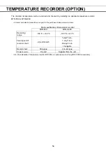
Page 59: ...of temperature recorder Main specifications of temperature recorder MTR 85H MTR G85C Recording range 100 o C 50 o C 100 o C 40 o C Feed speed of recorder chart 2 month batch 1 day 1 turn 7 day 1 turn 32 day 1 turn changable Record chart Strip type Circular type Power source Dry cell Supplied from the unit For the installation of temperature recorder MTR 85H an optional recorder fixing MDF S3085 is...

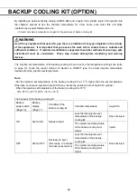
Page 60: ...g knob refer to page 10 Since the control method of injection is ON OFF type the actual injection temperature deviates from the injection set temperature Note Set the injection set temperature of the backup cooling kit to 10 o C higher than the set temperature Otherwise continuous injection of liquid CO2 may reduce the retention time of liquid CO2 cylinder When the injection set temperature of the...

Page 61: ...ser Both A and B Finless tube type Refrigerant Both A and B HFC mixed refrigerant Temperature controller Microcomputer control system Temperature display LCD Digital display Thermal sensor Platinum resistance Pt 1000 Ω Alarm High Alarm Low Alarm Power failure alarm Door alarm Remote alarm Remote alarm contact Allowable contact capacity DC 30 V 2 A Battery Lead storage battery DC 6 V 7200 mAh Auto ...

Page 62: ... Temperature control range 50 o C to 86 o C ambient temperature 30 o C no load Rated voltage AC 230 V 240 V Rated frequency 50 Hz Rated power consumption 1070 W 1120 W 1070 W 1130 W Noise level 52 dB A background noise 20 dB Maximum pressure 2850 kPa 3150 kPa Maximum cooling performance The chamber temperature can be reached at 86 o C at ambient temperature 30 o C with no load Note Specifications ...

Page 63: ... unit Unit interior No contamination Decontaminated Contaminated Others 3 Instructions for safe repair maintenance disposal of the unit a The unit is safe to work on b There is some danger see below Procedure to be adhered to in order to reduce safety risk indicated in b below Date Signature Address Division Telephone Product name Model Serial number Date of installation Ultra low temperature MDF ...

Page 64: ...apan LDCL000600 1 S0615 10116 2016 01 08 1 1 1 Sakata Oizumi Machi Ora Gun Gunma 370 0596 Japan EU countries only 0123 Panasonic Healthcare Co Ltd 2015 Panasonic Marketing Europe GmbH Panasonic Testing Centre Winsbergring 15 22525 Hamburg Germany ...

Reviews: