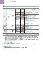
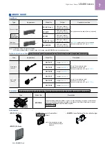
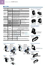
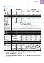
Panasonic LS-400 Series Manual Download Page 4

4

Digital Laser Sensor 

LS-400


SERIES

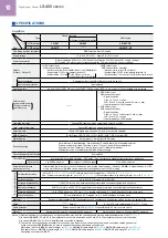
Easy setting, dual display

Equipped with 2 large 4-digit digital displays. While checking the current incident light intensity (red display), the 

optimal threshold value (green display) can be set easily.

10 mm 

0.394 in


thickness

Large jog switch

Threshold value setting display

Green LED, 4 digits (Max. display: 9999)

Current incident light intensity display

Red LED, 4 digits (Max. display: 9999)

Large MODE key

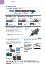
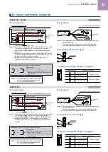
2 switches enable simple operation

Only two switches, the large MODE key and the large jog switch, are required for operation.

3

Pressing the switch 

selects or cancels the 

operating mode

Moving the switch from 

side to side allows items 

to be selected

Pressing the switch then 

confirms the selected 

setting

2

1

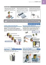
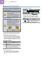
Threshold tracking function saves 

maintenance time

This function seeks 

changes in the light emitting 

amount resulting from 

changes in the environment 

over long periods (such 

as dust levels), so that 

the incident light intensity 

can be checked at desired 

intervals and the threshold 

values can be reset 

automatically. This helps to 

reduce the man-hours for 

maintenance.

Time

Current value

The amount of light

received when there 

is no object

Incident light intensity

Threshold value

Digital fiber sensor 

FX-500/300

 series

Digital pressure sensor 

DPS-400

 series

Up to 16 units can be 

connected together 

Note: Because the transmission method varies depending on the 

          amplifiers, check the instruction manual for the amplifiers when 

          connecting them. 

Wiring and space saving

The quick-connection cables enable reductions in wiring. 

(connector type) 

The connections and man-hours for the relay terminal 

setup can be reduced and valuable space is saved. 

Also, 

LS-400

 series amplifiers can of course be 

connected side-by-side with a connector type amplifier 

of 

FX-500/300

 series digital fiber sensors or 

DPS-400


series digital pressure sensors.

Note: Because the transmission method varies depending on the

          amplifiers, check the instruction manual for the amplifiers when

          connecting them.

*

CC-Link and CC-Link IE Field are a registered trademark of 

Mitsubishi Electric Corporation.

DeviceNet is a registered trademark of ODVA (Open DeviceNet 

Vender Association, Inc.).

EtherCAT is a registered trademark of Beckhoff Automation GmbH. 

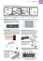
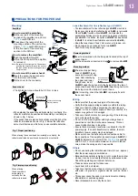
New release of type with upper communication functions to facilitate preventive maintenance!

LS-403

Network communication possible

Can connect to Open Network CC-Link IE Field / 

CC-Link / DeviceNet / EtherCAT via Communication

Unit for Open Network 

SC-GU3

 series. Monitoring and

various settings can be done from PLC, PC, etc.

しきい値

1ch

現在値

90

65

2ch

50

0

3ch

40

70

4ch

0

0

5ch

0

0

6ch

0

0

7ch

0

0

8ch

0

0

しきい値

9ch

現在値

0

0

10ch

0

0

11ch

0

0

12ch

0

0

13ch

0

0

14ch

0

0

15ch

0

0

16ch

0

0

LS-403/501

FX-501/502

FX-301/305

DPS-401/402

Current values 

of connected 

sensors are 

shown.

[Touch panel display example]

Threshold values of 

connected sensors are 

shown.

End unit

Digital laser sensor

Digital fiber sensor

Digital fiber sensor

Digital pressure sensor

Communication Unit 

for Open Network

SC-GU3 

series

Summary of Contents for LS-400 Series

Page 1: ...2022 6 Amplifier separated Digital Laser Sensor LS 400SERIES The contents of this catalog are as of October 2017 For the latest information please visit our company website...

Page 2: ...e type LS H21 Easy to use sealing type reflective tape available Easy to use sealing type reflective tape available 500 mm 19 685 in A spot diameter of approx 1 mm 0 039 in at a 1 000 mm 39 370 in sen...

Page 3: ...ighly reliable built in multiple turn type knob allows you to adjust the spot shape easily Easy and accurate adjustments A spot size adjuster is built into the back of the sensor head allowing the use...

Page 4: ...iers check the instruction manual for the amplifiers when connecting them Wiring and space saving The quick connection cables enable reductions in wiring connector type The connections and man hours f...

Page 5: ...load emission halt function and D CODE values can be stored in CUSTOM mode The settings are changed easily Emission halt function If you do not want to place a laser spot in the visual range of the im...

Page 6: ...11 in LS H22F Note 2 3 FDA IEC JIS NOTE Mounting bracket is not supplied with the sensor head Please select from the range of optional sensor head mounting brackets Notes 1 Obtained Korea s S mark cer...

Page 7: ...h 2 m 6 562 ft CN 74 C5 Length 5 m 16 404 ft Sub cable 2 core CN 72 C1 Length 1 m 3 281 ft 0 2 mm2 2 core cabtyre cable with connector on one end Cable outer diameter 3 3 mm 0 130 in CN 72 C2 Length 2...

Page 8: ...ve type Size 9 2 9 2 t 0 4 mm 0 362 0 362 t 0 016 in Bank selection unit FX CH NPN input type Setting for up to 16 laser sensors can be changed at once by means of external signals FX CH P PNP input t...

Page 9: ...F Ambient humidity 35 to 85 RH Storage 35 to 85 RH Ambient illuminance Incandescent light 3 000 x or less at the light receiving face Voltage withstandability 1 000 V AC for one min between all suppl...

Page 10: ...adjustment function Incorporated Timer function Incorporated with variable ON delay OFF delay One shot timer switchable either effective or ineffective Timer period 1 to 9 999 ms approx 0 5 ms approx...

Page 11: ...n sub cable does not have brown lead wire and blue lead wire The power is supplied from the connector of the main cable 2 The quick connection cable does not have a pink lead wire Terminal layout of c...

Page 12: ...nce However if the adjuster is turned too far it may be damaged Safe use of laser products For the purpose of preventing users from suffering Never use this product as a sensing device for personnel p...

Page 13: ...0 5 sec approx after the power supply is switched on Because the sensitivity is higher in U LG mode than in other modes it can be more easily affected by extraneous noise Check the operating environm...

Page 14: ...00 78 740 Amplifier LS 401 LS 401P LS 403 Amplifier LS 401 C2 LS 401P C2 11 0 433 10 0 394 75 2 953 27 8 1 094 3 0 118 30 1 181 24 0 945 Communication window Suitable for 35 mm 1 378 in width DIN rail...

Page 15: ...992 27 8 1 094 RF 31 9 2 0 362 9 2 0 362 2 3 2 0 126 holes 2 0 079 t 1 t 0 039 0 4 0 016 7 5 0 295 4 2 0 165 2 0 079 1 8 0 071 3 2 0 126 5 2 0 205 8 5 0 335 5 2 0 205 3 2 0 126 5 0 197 21 6 0 850 16 0...

Page 16: ...or mounting bracket for RF 230 Optional Assembly dimensions 40 1 575 4 5 0 177 28 3 1 114 19 3 0 760 8 3 0 327 50 3 1 980 61 3 2 413 7 0 276 49 3 1 941 5 0 197 40 1 575 t 2 t 0 079 10 0 394 10 0 394 3...

Page 17: ...sal sensor mounting stand Optional 25 5 1 004 10 0 394 2 6 6 0 260 mounting holes 45 1 772 32 1 260 Base PA 8 0 315 18 0 709 20 0 787 28 1 102 28 45 1 120 12 0 472 16 5 0 650 147 5 787 Note 1 44 5 1 7...

Page 18: ...e have obtained some intellectual properties such as patent rights with respect to such applications or that the described applications may not infringe any intellectual property rights such as patent...

Reviews: