

1
0
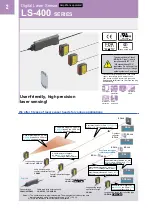
Digital Laser Sensor
LS-400
SERIES
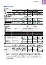
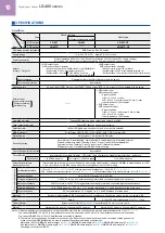
SPECIFICATIONS
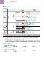
Amplifiers
Type
Connector type
Cable type
With upper communication function
Model
No. NPN output
LS-401
LS-403
LS-401-C2
Item
PNP output
LS-401P
–
LS-401P-C2
CE marking directive compliance
EMC Directive, RoHS Directive
Supply voltage
12 to 24 V DC ±10 % Ripple P-P 10 % or less
Power consumption
Normal operation: 950 mW or less (Current consumption 40 mA or less at 24 V supply voltage)
ECO mode: 780 mW or less (Current consumption 33 mA or less at 24 V supply voltage)
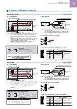
Outputs
(Output 1, Output 2)
<NPN output type>
NPN open-collector transistor
• Maximum sink current: 100 mA (
LS-401
□) (Note 2) , 50 mA (
LS-403
) (Note 3)
• Applied voltage: 30 V DC or less (between output and 0 V)
• Residual voltage: 1.5 V or less at 100 mA (Note 2) sink current
at 50 mA (Note 3) sink current (
LS-403
)
<PNP output type>
PNP open-collector transistor
• Maximum source current: 100 mA (Note 2)
• Applied voltage: 30 V DC or less (between output and +V)
• Residual voltage: 1.5 V or less [at 100 mA (Note 2) source current]
Output operation
Selectable either Light-ON or Dark-ON, with jog switch
Short-circuit protection
Incorporated
Response time
80 µs or less (H-SP), 150 µs or less (FAST), 500 µs or less (STD), 4 ms or less (U-LG) selectable with jog switch
External input
Laser emission halt
Full-auto teaching /
Limit teaching
–
<NPN output type>
NPN non-contact input
• Signal condition
High: +5 V to +V or open,
Low: 0 to +2 V (source current 0.5 mA or less)
• Input impedance: 10 kΩ approx.
<PNP output type>
PNP non-contact input
• Signal condition
High: +4 V to +V (sink current 3 mA or less)
Low: 0 to +0.6 V or open
• Input impedance: 10 kΩ approx.
Operation indicator
Orange LED (lights up when output 1 and output 2 are ON)
Laser emission indicator
Green LED (lights up during laser emission)
Select indicator
Yellow LED (lights up when either output 1 or output 2 is selected)
MODE indicator
RUN: Green LED, TEACH • L/D • TIMER • CUST • PRO: Yellow LED
Digital display
4 digit (green) + 4 digit (red) LED display
Sensitivity setting
Normal mode: 2-level teaching / Limit teaching / Full-auto teaching / Manual adjustment
Window comparator mode: Teaching (1-level, 2-level, 3-level) / Manual adjustment
Hysteresis mode: Teaching (1-level, 2-level, 3-level) / Manual adjustment
Differential mode: 5-level settings (
LS-403
: 8-level settings)
Fine sensitivity adjustment function
Incorporated
Timer function
Incorporated with variable ON-delay / OFF-delay / One shot timer, switchable either effective or ineffective.
Timer period
1 to 9,999 ms approx.
0.5 ms approx. 1 to 9,999 ms approx.
1 to 9,999 ms approx.
Automatic interference
prevention function
Incorporated [Up to four sets of sensor heads can be mounted close together. (However,
LS-401
□ is disabled when in H-SP
mode, up to two sets of
LS-403
can be mounted close together when in H-SP mode)]
Environmental resistance
Ambient temperature
–10 to +55 °C
+14 to +131 °F
(If 4 to 7 units are mounted close together: –10 to +50 °C
+14 to +122 °F
,
if 8 to 16 units are mounted close together: –10 to +45 °C
+14 to +113 °F
) (No dew condensation or icing allowed), Storage: –20 to +70 °C
4 to +158 °F
Ambient humidity
35 to 85 % RH, Storage: 35 to 85 % RH
Voltage withstandability
1,000 V AC for one min. between all supply terminals connected together and enclosure
Insulation resistance
20 MΩ, or more, with 250 V DC megger between all supply terminals connected together and enclosure
Vibration resistance
10 to 150 Hz frequency, 0.75 mm
0.030 in
double amplitude in X, Y and Z directions for two hours each
Shock resistance
98 m/s
2
acceleration (10 G approx.) in X, Y and Z directions five times each
Material
Enclosure: Heat-resistant ABS, Transparent cover: Polycarbonate, Push button switch: Acrylic, Jog switch: ABS
Cable
– (Note 4)
0.15 mm
2
5-core cabtyre cable, 2 m
6.562 ft
long
Cable extension
Extension up to total 100 m
328.084 ft
is possible with 0.3 mm
2
, or more, cable.
Weight
Net weight: 15 g approx., Gross weight: 20 g approx.
Net weight: 65 g approx., Gross weight: 75 g approx.
Notes: 1) Where measurement conditions have not been specified precisely, the conditions used were an ambient temperature of +23 °C
+73.4 °F
.
2) In case of
LS-401
(
P
), 50 mA if 5 to 8 amplifiers are connected in cascade, and 25 mA if 9 to 16 amplifiers are connected in cascade.
3) In case of
LS-403
, 25 mA if 5 to 16 amplifiers are connected in cascade.
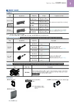
4) The cable is not supplied as an accessory for connector type. Be sure to purchase the optional quick-connection cables given below.
When connecting to
SC-GU3
series, be sure to purchase the optional cascading connector unit.
Main cable (4-core):
CN-74-C1
(cable length 1 m
3.281 ft
),
CN-74-C2
(cable length 2 m
6.562 ft
),
CN-74-C5
(cable length 5 m
16.404 ft
)
Sub cable (2-core):
CN-72-C1
(cable length 1 m
3.281 ft
),
CN-72-C2
(cable length 2 m
6.562 ft
),
CN-72-C5
(cable length 5 m
16.404 ft
)
Cascading connector unit:
SC-71


