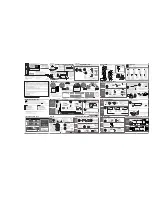
– 10 –
Control reference guide (continued)
Rear Panel
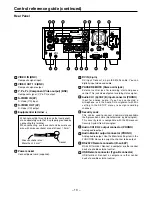
VIDEO
VIDEO
S-VIDEO
S-VIDEO
1
2
Y
CH1(A)
DV IN
RS-232C
USB
~ AC IN
PAUSE
REMOTE
CH2(B)
CH1
CH2
P
B
P
R
VIDEO IN
VIDEO OUT
AUDIO IN
AUDIO OUT
AUDIO
MON
DV IN (4-pin)
DV input. Connect a 4-pin IEEE1394 cable. You can
digitally input video and audio.
PAUSE REMOTE (Stereo mini jack)
External control jack for recording start and pause
control. This jack also outputs a recording status signal.
Audio CH1 (A)/CH2 (B) input connector (PHONO)
Input for analog audio. If you have connected a
microphone, use the Audio CH assignment with Mic
setting in the SETUP menus to assign recording
channels.
Security Lock
This can be used to connect a commercially-available
theft-prevention cable (manufactured by Kensington).
This security lock is compatible with the Microsaver
Security System from Kensington.
Audio CH1/CH2 output connector (PHONO)
Analog audio output.
Audio Monitor output connector (PHONO)
Analog audio output. Use the Monitor setting item in the
FUNCTION menus to assign the channel to be output.
RS-232C Remote connector (D-sub 9P)
RS-232C terminal. Connect a computer or other control
device to enable external control.
USB Remote connector (Type-B connector)
USB terminal. Connect a computer or other control
device to enable external control.
Power socket
Connect power cord (supplied).
When connecting this unit to any other component,
make absolutely sure that it is properly grounded by
connecting this terminal.
When connecting, use the socket and be sure to use
wire with a cross-sectional area of at least 1.0 mm
2
.
VIDEO IN (BNC)
Composite signal input.
VIDEO OUT 1/2 (BNC)
Composite signal output.
Y, P
B
, P
R
(Component Video output) (BNC)
Component signal (Y, P
B
, P
R
) output.
S-VIDEO IN (4P)
S-Video (Y/C) input.
S-VIDEO OUT (4P)
S-Video (Y/C) output.
Equipotential terminal
Cross-sectional area :
More than 1.0 mm
2
Socket


