62
KX-TG6051BXM/KX-TGA601BXM
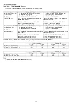
10.1.6.4. TEST RANGE Check
Circuit block which range is defective can be found by the following check.
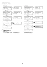
CHART1: Setting of TX Power and RX Sensitivity in Range Confirmation TX TEST, RX TEST
Note:
Adjustment and Test Mode Flow Chart
Item
BU (Base Unit) Check
HS (Handset) Check
Range Confirmation TX TEST
(TX Power check)
HS, BU Mode:
[Test Link Mode] (*1)
1. Register Regular HS to BU (to be checked).
2. Set BU to "Test Link mode".
3. Set Regular HS to "Test Link mode".
*Set TX Power and RX Sensitivity of the BU and the
Regular HS by CHART1.
* At distance of about 5 m between HS and BU,
Link OK = TX Power of the BU is OK.
No Link = TX Power of the BU is NG.
1. Register HS (to be checked) to Regular BU.
2. Set Regular BU to "Test Link mode".
3. Set HS to "Test Link mode".
*Set TX Power and RX Sensitivity of the HS and the
Regular BU by CHART1.
* At distance of about 5 m between HS and BU,
Link OK = TX Power of the HS is OK.
No Link = TX Power of the HS is NG.
Range Confirmation RX TEST
(RX sensitivity check)
HS, BU Mode:
[Test Link Mode] (*1)
1. Register Regular HS to BU (to be checked).
2. Set BU to "Test Link mode".
3. Set Regular HS to "Test Link mode".
*Set TX Power and RX Sensitivity of the BU and Regular
HS by CHART1.
* At distance of about 5 m between HS and BU,
Link OK= RX Sensitivity of the BU is OK.
No Link = RX Sensitivity of the BU is NG.
1. Register HS (to be checked) to Regular BU.
2. Set Regular BU to "Test Link mode".
3. Set HS to "Test Link mode".
* Set TX Power and RX Sensitivity of Checking_HS and
Regular_BU by CHART1.
* At distance of about 5 m between HS and BU,
Link OK= RX Sensitivity of the HS is OK.
No Link = RX Sensitivity of the HS is NG
BU (to be checked)
Regular_HS
TX Power
RX Sens.
TX Power
RX Sens.
BU (Base Unit) TX Power Check
High
High
High
Low
BU (Base Unit) RX Sensitivity Check
High
High
Low
High
HS (to be checked)
Regular_BU
TX Power
RX Sens.
TX Power
RX Sens.
HS (Handset) TX Power Check
High
High
High
Low
HS (Handset) RX Sensitivity Check
High
High
Low
High
Summary of Contents for KX-TG6051BXM
Page 2: ...2 KX TG6051BXM KX TGA601BXM ...
Page 6: ...6 KX TG6051BXM KX TGA601BXM 3 Specifications ...
Page 30: ...30 KX TG6051BXM KX TGA601BXM 4 10 Signal Route ...
Page 31: ...31 KX TG6051BXM KX TGA601BXM RF part signal route ...
Page 36: ...36 KX TG6051BXM KX TGA601BXM 7 1 2 Programming using the Direct Commands ...
Page 38: ...38 KX TG6051BXM KX TGA601BXM 7 3 Error Messages ...
Page 39: ...39 KX TG6051BXM KX TGA601BXM 7 4 Troubleshooting ...
Page 40: ...40 KX TG6051BXM KX TGA601BXM ...
Page 41: ...41 KX TG6051BXM KX TGA601BXM ...
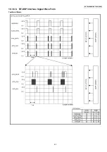
Page 63: ...63 KX TG6051BXM KX TGA601BXM 10 1 6 5 RF DSP Interface Signal Wave Form Test Burst Mode ...
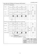
Page 64: ...64 KX TG6051BXM KX TGA601BXM Test Burst Mode ...
Page 72: ...72 KX TG6051BXM KX TGA601BXM ...
Page 73: ...73 KX TG6051BXM KX TGA601BXM 11 1 2 Handset ...
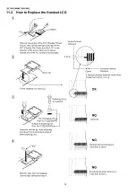
Page 74: ...74 KX TG6051BXM KX TGA601BXM 11 2 How to Replace the Handset LCD ...
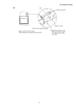
Page 75: ...75 KX TG6051BXM KX TGA601BXM ...
Page 87: ...87 KX TG6051BXM KX TGA601BXM Memo ...
Page 92: ...92 KX TG6051BXM KX TGA601BXM Memo ...
Page 96: ...96 KX TG6051BXM KX TGA601BXM Memo ...
Page 100: ...100 KX TG6051BXM KX TGA601BXM Memo ...
Page 106: ...106 KX TG6051BXM KX TGA601BXM 15 3 Explanation of IC Terminals RF Part 15 3 1 IC701 ...
Page 107: ...107 KX TG6051BXM KX TGA601BXM 15 3 2 IC801 ...
Page 111: ...111 KX TG6051BXM KX TGA601BXM 16 3 Accessories and Packing Materials ...

