29
KX-TG6051BXM/KX-TGA601BXM
4.9.3.
5.8 GHz PA (Power Amplifier), 5.8 GHz LNA (Low Noise Amplifier) and Antenna
Switch Circuit
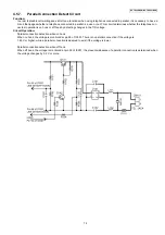
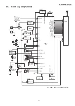
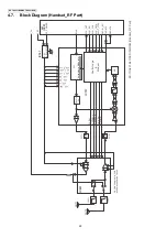
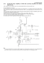
IC801 includes PA (Power Amplifier) block, LNA (Low Noise Amplifier) Block and Antenna Switch Circuit.
PA block amplifies 5.8 GHz TX signal.
5.8 GHz TX signal from 5.8 GHz RF IC (IC701) is filtered by 5.8 GHz-BPF FL711, and amplified by PA (Power Amplifier) block of
IC801. After that, it is supplied to Antenna Switch block from pin 24 of IC801. V_PA is approximately 4.0 V at base unit, and 3.3 V at
handset.
LNA block amplifies receiving 5.8 GHz signal. 5.8 GHz RX signal from Antenna Switch block of IC801 is amplified by LNA block and
is supplied to IC701 through 5.8 GHz-BPF (FL721).
Antenna Switch block of IC801 switches for RF signals by ANTSEL_A and ANTSEL_B from IC701.
IC701 checks RSSI (Received Signal Strength Indicator), and selects better receiving condition antenna.
At RX mode, RX signal is lead from selected antenna to LNA block.
On the other hand, 5.8 GHz TX signal from PA block is lead to selected antenna at RX mode.
Note:
The exposed GND_PLATE on the bottom of IC801 supplies the circuit ground(s) for the entire chip. It is very important that a
good solder connection is made between this GND_PLATE and the ground plane of PCB underlying the IC801.
Summary of Contents for KX-TG6051BXM
Page 2: ...2 KX TG6051BXM KX TGA601BXM ...
Page 6: ...6 KX TG6051BXM KX TGA601BXM 3 Specifications ...
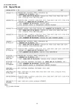
Page 30: ...30 KX TG6051BXM KX TGA601BXM 4 10 Signal Route ...
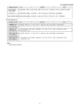
Page 31: ...31 KX TG6051BXM KX TGA601BXM RF part signal route ...
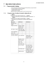
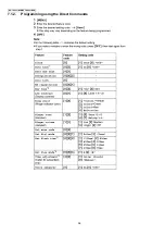
Page 36: ...36 KX TG6051BXM KX TGA601BXM 7 1 2 Programming using the Direct Commands ...
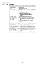
Page 38: ...38 KX TG6051BXM KX TGA601BXM 7 3 Error Messages ...
Page 39: ...39 KX TG6051BXM KX TGA601BXM 7 4 Troubleshooting ...
Page 40: ...40 KX TG6051BXM KX TGA601BXM ...
Page 41: ...41 KX TG6051BXM KX TGA601BXM ...
Page 63: ...63 KX TG6051BXM KX TGA601BXM 10 1 6 5 RF DSP Interface Signal Wave Form Test Burst Mode ...
Page 64: ...64 KX TG6051BXM KX TGA601BXM Test Burst Mode ...
Page 72: ...72 KX TG6051BXM KX TGA601BXM ...
Page 73: ...73 KX TG6051BXM KX TGA601BXM 11 1 2 Handset ...
Page 74: ...74 KX TG6051BXM KX TGA601BXM 11 2 How to Replace the Handset LCD ...
Page 75: ...75 KX TG6051BXM KX TGA601BXM ...
Page 87: ...87 KX TG6051BXM KX TGA601BXM Memo ...
Page 92: ...92 KX TG6051BXM KX TGA601BXM Memo ...
Page 96: ...96 KX TG6051BXM KX TGA601BXM Memo ...
Page 100: ...100 KX TG6051BXM KX TGA601BXM Memo ...
Page 106: ...106 KX TG6051BXM KX TGA601BXM 15 3 Explanation of IC Terminals RF Part 15 3 1 IC701 ...
Page 107: ...107 KX TG6051BXM KX TGA601BXM 15 3 2 IC801 ...
Page 111: ...111 KX TG6051BXM KX TGA601BXM 16 3 Accessories and Packing Materials ...

