68
KX-TG6051BXM/KX-TGA601BXM
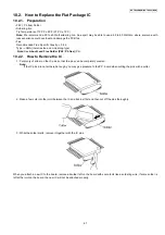
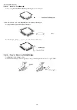
10.2.3. How to Install the IC
1. Temporarily fix the FLAT PACKAGE IC, soldering the two marked pins.
*Check the accuracy of the IC setting with the corresponding soldering foil.
2. Apply flux to all pins of the FLAT PACKAGE IC.
3. Solder the pins, sliding the soldering iron in the direction of the arrow.
10.2.4. How to Remove a Solder Bridge
1. Lightly resolder the bridged portion.
2. Remove the remaining solder along the pins using a soldering iron as shown in the figure below.
Summary of Contents for KX-TG6051BXM
Page 2: ...2 KX TG6051BXM KX TGA601BXM ...
Page 6: ...6 KX TG6051BXM KX TGA601BXM 3 Specifications ...
Page 30: ...30 KX TG6051BXM KX TGA601BXM 4 10 Signal Route ...
Page 31: ...31 KX TG6051BXM KX TGA601BXM RF part signal route ...
Page 36: ...36 KX TG6051BXM KX TGA601BXM 7 1 2 Programming using the Direct Commands ...
Page 38: ...38 KX TG6051BXM KX TGA601BXM 7 3 Error Messages ...
Page 39: ...39 KX TG6051BXM KX TGA601BXM 7 4 Troubleshooting ...
Page 40: ...40 KX TG6051BXM KX TGA601BXM ...
Page 41: ...41 KX TG6051BXM KX TGA601BXM ...
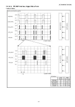
Page 63: ...63 KX TG6051BXM KX TGA601BXM 10 1 6 5 RF DSP Interface Signal Wave Form Test Burst Mode ...
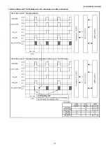
Page 64: ...64 KX TG6051BXM KX TGA601BXM Test Burst Mode ...
Page 72: ...72 KX TG6051BXM KX TGA601BXM ...
Page 73: ...73 KX TG6051BXM KX TGA601BXM 11 1 2 Handset ...
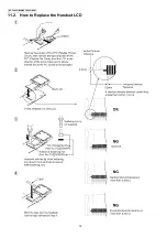
Page 74: ...74 KX TG6051BXM KX TGA601BXM 11 2 How to Replace the Handset LCD ...
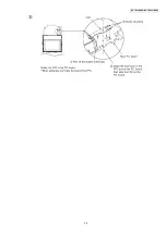
Page 75: ...75 KX TG6051BXM KX TGA601BXM ...
Page 87: ...87 KX TG6051BXM KX TGA601BXM Memo ...
Page 92: ...92 KX TG6051BXM KX TGA601BXM Memo ...
Page 96: ...96 KX TG6051BXM KX TGA601BXM Memo ...
Page 100: ...100 KX TG6051BXM KX TGA601BXM Memo ...
Page 106: ...106 KX TG6051BXM KX TGA601BXM 15 3 Explanation of IC Terminals RF Part 15 3 1 IC701 ...
Page 107: ...107 KX TG6051BXM KX TGA601BXM 15 3 2 IC801 ...
Page 111: ...111 KX TG6051BXM KX TGA601BXM 16 3 Accessories and Packing Materials ...

