


2
How to turn on Network Camera for Installation
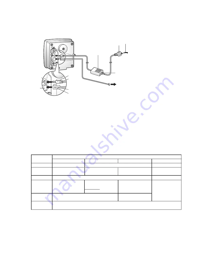
Connect the DC plug of the AC adaptor to the DC IN jack
(1.)
and Category 5 straight/cross cable to the
Ethernet port
(2.)
. Attach the AC cord to the AC adaptor
(3.)
. Connect the AC plug to the power outlet
(4.)
.
Preparing the Network Parameters for the Network Camera
Before starting to set up the network parameters of Network Camera, please make note of corresponding
network parameters.
AC adaptor
AC cord
DC IN
jack
Power
Outlet
Ethernet
port
DC Plug
(1.)
(3.)
(4.)
Category 5 straight/cross cable
To Network
(2.)
Notes
AC adaptor is used as the main
disconnect device, ensure that the
power outlet is located/installed near
the equipment and is easily accessible.
•
Use Only with specified Panasonic
AC adaptor PSLP1238
(Order No. PSLP1238Z).
•
AC Adaptor is for indoor use only.
•
After you have finished setting up the
Network Camera, please go to Page 5
in this Getting Started for Outdoor
Cabling and Mounting.
•
When you set up the Network Camera
in
[Type 3]
, please connect the Network
Camera temporarily in
[Type 1]
,
[Type 2]
or
[Type 4]
.
•
[Type 1]
Please ask the network administrator for the network parameters.
[Type 2]
Please ask the network administrator for the network parameters.
[Type 3]
Please ask the ISP for the network parameters.
[Type 4]
Please install the Network Camera in the default condition. Please set the PC "192.168.0.250" (IP address) and
"255.255.255.0" (Subnet Mask). Please refer to Page 24 in the Operating Instructions.
It can restrict the transmit bandwidth.
Select from 0.1 to Unlimited Mbit/s.
Max.
Bandwidth
Usage
Parameters
Network Camera Configuration Type
Port No.*
1
IP address
Subnet Mask
Default
Gateway
DNS
Server 1, 2
Check [Static], and set the
static private IP address.
192.168.0.253 (default)
255.255.255.0 (default)
Check [Static], and set the
static global IP address.*
4
Check [Static], and set the
static private IP address.*
3
Set Default Gateway
address.
You do not need to
set up.
Set DNS server address.
[Type 1]
[Type 2]
[Type 3]
[Type 4]
Set Default Gateway
address.*
4
Set DNS server address.*
4
Set the private IP address
of the broadband router (on
your network), not of the
gateway of the ISP. *
3
80 (default)*
2
80 (default)
80 (default)
Set the Subnet Mask fitted to your network.
Network Parameters Table
When you use more than one Network Camera with a broadband router, each Network Camera needs its own port no. The
broadband router needs the Port Forwarding feature. Refer to Page 32 in the Operating Instructions.
Many ISP's intentionally block port no. 80 to guard against certain network viruses. If your ISP blocks port no. 80, please
substitute another unused port no.
Refer to the broadband router's manual for the Port Forwarding feature.
When you use Network Camera in DHCP feature, check [DHCP] and enter the Host Name if the ISP requires. If you
automatically get the address of Default Gateway and DNS server from DHCP server, you do not need to set up.
*
1
*
2
*
3
*
4