54
KX-FC265CX-S
8.6.
Installing the Recording Paper
The unit can hold up to 20 sheets of 64 g/m
2
to 80 g/m
2
paper.
Note for recording paper:
• Do not use the following types of paper:
- Paper with a cotton and/or fibre content that is over 20%,
such as letterhead paper or paper used for resumes
- Extremely smooth or shiny paper, or paper that is highly
textured
- Coated, damaged or wrinkled paper
- Paper with foreign objects attached, such as tabs or sta-
ples
- Paper which has dust, lint or oil stains
- Paper that will melt, vaporize, discolour, scorch or emit
dangerous fumes near 200
°
C, such as vellum paper.
These materials may transfer onto the fusing roller and
cause damage.
- Moist paper
• Some paper only accepts print on one side. Try using the
other side of the paper if you are not happy with the print
quality, or if misfeeding occurs.
• For proper paper feeding and best print quality, we recom-
mend using long-grained paper.
• Do not use paper of different types or thickness at the same
time. This may cause a paper jam.
• Avoid double-sided printing.
• Do not use paper printed from this unit for double-sided
printing with other copiers or printers.
This may cause a paper jam.
• To avoid curling, do not open paper packs until you are
ready to use the paper. Store unused paper in the original
packaging, in a cool and dry location.
• For customers who live in high humidity areas:
Please be sure to store paper in an air-conditioned room at
all times. If you print using moist paper, it may cause paper
jam.
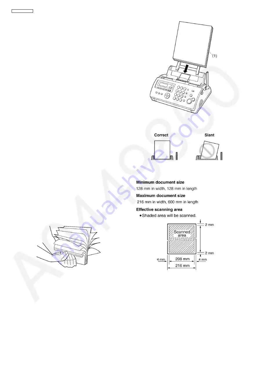
1. Fan the paper to prevent paper jams.
2. Insert the paper gently, print-side down (1).
• Do not force the paper into the paper tray.
• If the paper is not inserted correctly, remove all of the
installed paper, and re-install it gently. Otherwise the
paper may jam.
Note:
• Remove all of the installed paper before adding paper.
Document requirements
Document weight
• single sheet:
45 g/m
2
to 90 g/m
2
• multiple sheet:
60 g/m
2
to 80 g/m
2
Summary of Contents for KX-FC265CX-S
Page 20: ...20 KX FC265CX S 6 4 2 Block Diagram ...
Page 22: ...22 KX FC265CX S ...
Page 58: ...58 KX FC265CX S Note Refer to Program Mode Table P 99 ...
Page 66: ...66 KX FC265CX S 11 2 Cordless Handset ...
Page 69: ...69 KX FC265CX S 11 3 2 Service Mode Settings Note The above values are the default values ...
Page 77: ...77 KX FC265CX S Countermeasure ...
Page 78: ...78 KX FC265CX S REFERENCE Test Mode P 59 ...
Page 79: ...79 KX FC265CX S REFERENCE Test Mode P 59 ...
Page 80: ...80 KX FC265CX S REFERENCE Test Mode P 59 ...
Page 81: ...81 KX FC265CX S REFERENCE Test Mode P 59 ...
Page 82: ...82 KX FC265CX S ...
Page 83: ...83 KX FC265CX S REFERENCE Test Mode P 59 ...
Page 84: ...84 KX FC265CX S REFERENCE Test Mode P 59 ...
Page 88: ...88 KX FC265CX S ...
Page 113: ...113 KX FC265CX S ...
Page 120: ...120 KX FC265CX S I O and Pin No Diagram ...
Page 122: ...122 KX FC265CX S Other NG example while the power is ON and the LCD displays the following ...
Page 123: ...123 KX FC265CX S 12 5 5 2 NG Example ...
Page 127: ...127 KX FC265CX S 12 5 7 2 Troubleshooting Flow Chart ...
Page 133: ...133 KX FC265CX S 12 5 11 Thermal Head Section Note Refer to Thermal Head P 21 ...
Page 142: ...142 KX FC265CX S 13 Service Fixture Tools ...
Page 147: ...147 KX FC265CX S 14 3 Disassembly Procedure 14 3 1 How to Remove the Image Sensor CIS ...
Page 148: ...148 KX FC265CX S 14 3 2 How to Remove the Thermal Head ...
Page 149: ...149 KX FC265CX S ...
Page 150: ...150 KX FC265CX S 14 3 3 How to Remove the Bottom Frame ...
Page 151: ...151 KX FC265CX S 14 3 4 How to Remove the P C Boards and Speaker ...
Page 152: ...152 KX FC265CX S 14 3 5 How to Remove the Power Supply Board and AC Cord ...
Page 153: ...153 KX FC265CX S 14 3 6 How to Remove the Gear Block and Separation Roller ...
Page 154: ...154 KX FC265CX S 14 3 7 How to Remove the Gears Motors and Arms of the Gear Block ...
Page 155: ...155 KX FC265CX S ...
Page 156: ...156 KX FC265CX S 14 3 8 How to Remove the Charger Board A ...
Page 157: ...157 KX FC265CX S 14 3 9 How to Remove the Back Cover ...
Page 158: ...158 KX FC265CX S 14 3 10 How to Remove the Platen Roller and Lock Lever ...
Page 159: ...159 KX FC265CX S ...
Page 160: ...160 KX FC265CX S 14 3 11 How to Remove the Pickup Roller and Antenna ...
Page 161: ...161 KX FC265CX S 14 3 12 How to Remove the Operation Panel ...
Page 162: ...162 KX FC265CX S 14 3 13 How to Remove the Operation Board MIC Board and LCD ...
Page 163: ...163 KX FC265CX S 14 3 14 How to Remove the Separation Holder and Exit Roller ...
Page 164: ...164 KX FC265CX S 14 3 15 Installation Position of the Lead Wires 14 3 15 1 Lower Section ...
Page 165: ...165 KX FC265CX S ...
Page 166: ...166 KX FC265CX S ...
Page 167: ...167 KX FC265CX S ...
Page 168: ...168 KX FC265CX S 14 3 15 2 Operation Panel Section ...
Page 169: ...169 KX FC265CX S 14 3 15 3 Back Cover Section ...
Page 170: ...170 KX FC265CX S 14 3 16 How to Remove the Cordless Handset Board ...
Page 171: ...171 KX FC265CX S 14 3 16 1 How to Replace the LCD ...
Page 200: ...200 KX FC265CX S 17 1 7 Cordless Handset Board ...
Page 205: ...205 KX FC265CX S 17 4 Test Chart 17 4 1 ITU T No 1 Test Chart ...
Page 206: ...206 KX FC265CX S 17 4 2 ITU T No 2 Test Chart ...
Page 207: ...207 KX FC265CX S 17 4 3 Test Chart ...
Page 237: ...237 KX FC265CX S Memo ...
Page 239: ...239 KX FC265CX S Memo ...
Page 266: ...266 KX FC265CX S ...
Page 267: ...267 KX FC265CX S YK KXFC265CXS ...


