

•
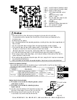
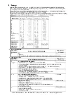
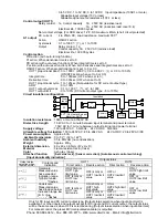
OUT1 : Control output 1 (Heating output)
• OUT2 : Control output 2 (Cooling output)
• RELAY : Relay contact output
• V/A
: DC voltage output/DC current
output
• S
: Non-contact relay output
• A1
: Alarm 1 output
• EVT : Event output (A2 output, Heater
burnout alarm output)
• CT
: CT input
• TC
: Thermocouple
• RTD : Resistance temperature detector
•
DC
: DC current, DC voltage
•
RS-485: Serial communication
(Fig. 4-1)
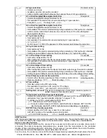
Notice
•
The terminal block of the KT4 Series is designed to be wired from the left side.
The lead wire must be inserted from the left side of the terminal, and fastened by the
terminal screw.
•
Dotted lines show options.
•
Use a thermocouple and compensating lead wire according to the sensor input specification of
this controller.
•
Use the 3-wire RTD which corresponds to the input specification of this controller.
•
This controller does not have built-in power switch, circuit breaker or fuse. Therefore, it is
necessary to install them in the circuit near the external controller.
(Recommended fuse: Time-lag fuse, rated voltage 250V AC, rated current 2A)
•
For a 24V AC/DC power source, do not confuse polarity when using direct current (DC).
•
When using a relay contact output type, use a relay according to the capacity of the load to
protect the built-in relay contact.
•
When wiring, keep input wires (thermocouple, RTD, etc.) away from AC sources or load wires
to avoid external interference.
•
If A2 and Heater burnout alarm are applied together, they share common output terminals.
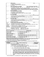
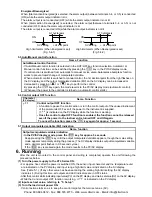
Lead wire solderless terminal
Use a solderless terminal with an insulation sleeve in which an M3 screw fits as shown below.
The torque is approximately 0.6N•m to 1.0N•m.
Solderless
terminal
Manufacturer
Model
Tightening
torque
Nichifu Terminal Industries CO.,LTD.
1.25Y-3
Y type
Japan Solderless Terminal MFG CO.,LTD.
VD1.25-B3A
0.6N•m
Nichifu Terminal Industries CO.,LTD.
1.25-3
Max. 1.0N•m
Round type
Japan Solderless Terminal MFG CO.,LTD.
V1.25-3
(Fig. 4-2)
Option: Heater burnout alarm
(1)
This alarm is not usable for detecting heater current
under phase control.
(2)
This alarm is not usable for
detecting 3-phase
heater current.
(3) Use the current transformer (CT) provided, and pass one
lead wire of the heater circuit into the hole of the CT.
(4) When wiring, keep CT wire away from AC sources
or load wires to avoid the external interference.
(Fig. 4-3)
CT input Terminal
Power
supply
Heater
CT
(11)
(12)
5.
8mm
or less
3.2mm
5.
8mm
or less
3.2mm
Phone: 800.894.0412 - Fax: 888.723.4773 - Web: www.clrwtr.com - Email: [email protected]


