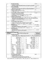
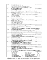
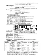


Thermocouple and RTD input
Input
Input range
Indication range
Control range
–199.9 to 400.0
–199.9 to 450.0
–205.0 to 450.0
K
,
T
–199.9 to 750.0
–199.9 to 850.0
–209.0 to 850.0
–199.9 to 850.0
–199.9 to 900.0
–210.0 to 900.0
–200 to 850
–210 to 900
–210 to 900
–199.9 to 999.9
–199.9 to 999.9
–211.0 to 1099.9
Pt100
–300 to 1500
–318 to 1600
–318 to 1600
–199.9 to 500.0
–199.9 to 550.0
–206.0 to 550.0
–200 to 500
–207 to 550
–207 to 550
–199.9 to 900.0
–199.9 to 999.9
–211.0 to 999.9
JPt100
–300 to 900
–312 to 1000
–312 to 1000
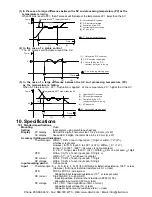
Indication range and Control range for the thermocouple inputs except the above:
[Input range low limit value – 50 (100 )] to [input range high limit value + 50 (100 )]
DC current and voltage input
Indication range
: [Scaling low limit value – Scaling span x 1%] to [Scaling high limit value
+Scaling span x 10%]
(If the input value is out of the range –1999 to 9999, the PV display flashes
“
” or “
”)
Control range
: [Scaling low limit value – Scaling span x 1%] to [Scaling high limit value
+Scaling span x 10%]
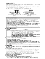
DC input disconnection
: When DC input is disconnected, PV display flashes “
” for 4 to
20mA DC and 1 to 5V DC inputs, and “
” for 0 to 1V DC input.
For 0 to 20mA DC, 0 to 5V DC and 0 to 10V DC inputs, the PV display
indicates the value corresponding with 0mA or 0V input.
[Burnout]
: When the thermocouple or RTD input is burnt out, OUT1 is turned OFF (for DC current
output type, OUT1 low limit value) and PV display flashes “
”.
[Self-diagnosis]
: The CPU is monitored by a watchdog timer, and when an abnormal status is
found on the CPU, the controller is switched to warm-up status.
[Automatic cold junction temperature compensation] (Only thermocouple input type)
This detects the temperature at the connecting terminal between the thermocouple and instrument,
and always keeps it set to the same status as when the reference junction is located at 0 (32
)
.
[Power failure countermeasure]
:
The setting data is backed up in the non-volatile memory.
[Warm-up indication]
After the p ower supply to the instrument is turned on, the sensor input character an d
temperature unit are indicated on the PV display and input range high limit value is indicated on
the SV display for 3 seconds.
For DC current and voltage inputs, the scaling high limit value is indicated.
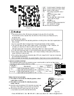
Accessories included
: Screw type mounting bracket 1 set, Instruction manual 1 copy
CT (Current transformer); For rating 5A, 10A, 20A (AKT4815) 1 piece
For rating 50A,
(AKT4816) 1 piece
Accessories sold separately
: Terminal cover (AKT4801) 1 piece, 50
shunt resistor (AKT4810) 1 piece
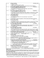
10.2 Optional specifications
Alarm 2 (A2)
If A2 and Heater burnout alarm are applied together, they utilize common output terminals.
Action
: ON/OFF action
Hysteresis
: 0.1 to 100.0
( ), or 1 to 1000
Output
: Relay contact, 1a
Control capacity, 3A 250V AC (Resistive load)
Electrical life, 100,000 cycles
Heater burnout alarm (including sensor burnout alarm)
Watches the heater current with CT (current transformer), and detects the burnout.
This alarm is also activated when indication is overscale and underscale.
(To detect Heater burnout, a CT for 50A can also be used for 5A, 10A and 20A ratings, however, this
is not suitable for small ampere ratings due to a low degree of accuracy. For a 20A rating or less, use
a CT designated for 20A.)
This option cannot be applied to DC current output type.
If A2 and Heater burnout alarm are applied together, they utilize common output terminals.
Rating
: 5A, 10A, 20A, 50A (Must be specified)
Setting range : 5A, 0.0 to 5.0A (Off when set to 0.0) 10A, 0.0 to 10.0A (Off when set to 0.0)
20A, 0.0 to 20.0A (Off when set to 0.0) 50A, 0.0 to 50.0A (Off when set to 0.0)
Setting accuracy : Within 5% of the rated value
Action
: ON/OFF action
Output
: Relay contact 1a
Control capacity, 3A 250V AC (resistive load)
Electrical life, 100,000 cycles
Phone: 800.894.0412 - Fax: 888.723.4773 - Web: www.clrwtr.com - Email: [email protected]


