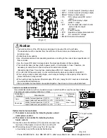
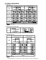
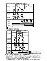
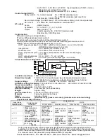


Energized/Deenergized
When [Alarm action Energized] is selected, the alarm output (between terminals 3-4, or 3-5) is conducted
(ON) while the alarm output indicator is lit.
The alarm output is not conducted (OFF) while the alarm output indicator is not lit.
When [Alarm action De energized] is se lected, the alarm output (betwee n terminals 3-4, or 3-5) is not
conducted (OFF) while the alarm output indicator is lit.
The alarm output is conducted (ON) while the alarm output indicator is not lit.
Hig h limit alarm (When Energized is set) High limit alarm (When Deenergized is set)
(Fig. 5.4-1) (Fig. 5.4-2)
5.5 Auto/Manual control function
Name, Function
Auto/Manual control function
• If Auto/Manual control function is selected in the OUT/OFF key function selection, Automatic or
Manual control function can be switched by pressing the
key in the PV/SV display mode.
If control action is switched from automatic to manual or vice versa, balanceless-bumpless function
works to prevent rapid change of manipulated variable.
When automatic control is switched to manual control, the 1st decimal point from the right flashes on
the SV display, and the output manipulated variable (MV) on the SV display can be increased or
decreased by pressing
or
key to perform the control.
By pressing the
key again, the mode reverts to the PV/SV display mode (automatic control).
(Whenever the power to the controller is turned on, automatic control starts.)
5.6 Control output OFF function
Character
(PV display)
Name, Function
Control output OFF function
• A function to pause the control action or turn the control output of the unused instrument
of the plural units OFF even if the power to the instrument is supplied.
[
] is indicated on the PV display while the function is working.
•
Once the control output OFF function is enabled, the function cannot be released
even if the power to the instrument is turned OFF and ON again.
To cancel the function, press the
key again for approx. 1 second.
5.7 Output manipulated variable (MV) indication
Name, function
Output manipulated variable indication
•
In the PV/SV display mode, press the
key for approx. 3 seconds.
Keep pressing the
key until the output manipulated variable appears, though the main setting
mode appears temporarily during the process. (The SV display indicates output manipulated variable
and a decimal point flashes in 0.5 second cycles.)
If the
key is pressed again, the mode reverts to the PV/SV display.
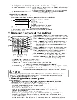
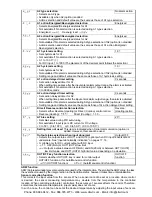
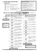
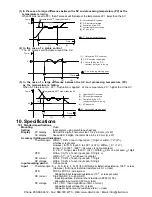
6. Running
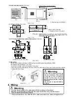
After the unit is mounte d to the control panel and wiring is completed, operate the unit following the
procedures below.
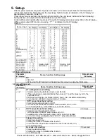
(1) Turn the power supply to the KT4 Series ON.
• For approx. 3sec after the power is switched ON, the sensor input character and the temperature unit
are indicated on the PV display and input range high limit value is indicated on the SV display.
See (Table 5-1). (If any other value has been set during the scaling high limit setting, the SV display
indicates it.) During this time, all outputs and LED indicators are in OFF status.
• After that, control starts indicating input value(PV) on the PV display, and main set value(SV) on the SV display.
• While the Control output OFF function is working,
is indicated on the PV display.
(2) Input each set value, referring to “5. Setup”.
(3) Turn the load circuit power ON.
Control action starts so as to keep the control target at the main set value (SV).
OFF
ON
A1 hysteresis
SV setting
+ A1 set point
OFF
ON
SV setting
+ A1 set point
A1 hysteresis
Phone: 800.894.0412 - Fax: 888.723.4773 - Web: www.clrwtr.com - Email: [email protected]


