background image

3.3 Start Window

WUME-SCLGCT-3

3-4

3.3 Start Window

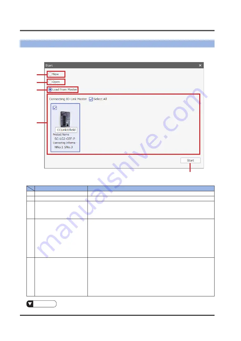
This window is used to select appropriate start options and start 

SC-LG-CEF Configuration 

Tool

.

1

2

3

4

5

Name

Description

1

New

Select this option to set up a new IO-Link master or IO-Link device offline.

2

Open

Select this option to open the file of a project that has been set up before.

3

Load from Master

Select this option to load data from an IO-Link master that is connected to 

the PC via a PLC.

When this option is selected, the "Connecting IO-Link Master" area can be 

manipulated.

4

Connecting IO-Link Master

A list of IO-Link masters that are connected to the PC via a PLC is dis-

played.

You can select a desired IO-Link master by selecting the check box on the 

top left of the frame of the device.

The product name and connecting information [NNo. (network No.), SNo. 

(station number)] are displayed. Select the check box on the top left of the 

frame of the master that you want to set up.

By clicking the Select All check box, you can select or cancel all the IO-Link 

masters that are displayed.

5

Start

After selecting New, Open, or Load from Master, click this button to start 

SC-LG-CEF Configuration Tool

.


If you select New and then click the Start button, you will be prompted to 

select the IO-Link master to be added.


If you select Open and then click the Start button, the previously set con-

ditions will be displayed.


If you select Load from Master and then click the Start button, the data 

of the selected IO-Link master(s) will be loaded. If none of the connected 

IO-Link masters is selected, the Start button will be grayed out.

Reference

For information about how to add IO-Link masters offline, refer to 

“4.1 Master Addition Function”

.

Summary of Contents for IO-Link SC-LG-CEF

Page 1: ...2023 1 panasonic net id pidsx global IO Link Configuration Tool SC LG CEF Configuration Tool User s Manual WUME SCLGCT 3 ...

Page 2: ...WUME SCLGCT 3 2 MEMO ...

Page 3: ...anual has undergone strict quality control but should you discover any dubious infor mation mistakes misplaced pages or missing pages please contact your local dealer 4 CC Link IE Field is a registered trademark of Mitsubishi Electric Corporation and a trademark managed by CC Link Partner Association 5 GX Works3 is a registered trademark or trademark of Mitsubishi Electric Corporation 6 Windows is...

Page 4: ...er explains the system environment system overview and connections 3 Name and Function of Each Window This chapter explains the name and function of each con figuration window 4 Other Functions This chapter explains the master addition removal and as signment functions project creation and saving functions network number setting function and other functions 5 Messages This chapter explains confirm...

Page 5: ...3 5 3 4 1 Master Port Configuration 3 5 3 4 2 Select Device Window 3 8 3 5 Master Information Window 3 10 3 6 Device Monitoring Window 3 11 3 7 Device Setup Window 3 12 3 8 Device Diagnosis Window 3 13 3 9 Device Information Window 3 14 3 10 Option Window 3 15 3 11 Version Information Window 3 16 4 Other Functions 4 1 4 1 Master Addition Function 4 2 4 2 Master Removal Function 4 3 4 3 Master Assi...

Page 6: ...WUME SCLGCT 3 6 MEMO ...

Page 7: ...1 1 1 Before Using This Product 1 1 Handling Precautions 1 2 1 2 Terminology 1 2 1 3 Overview 1 3 1 4 Software License Agreement 1 4 ...

Page 8: ...ge capacity open field network using Ethernet 1000BASE T Cyclic transmission A function that periodically exchanges data between stations on the same network in the data link layer Transient transmission A function that uses the read write instructions of the program at the lo cal station to read and write data from to remote stations and commu nicate with remote stations via peripheral devices in...

Page 9: ...ce and each of the systems connected to high level buses Port An IO Link communication channel port 1 3 Overview SC LG CEF Configuration Tool has the following functions IO Link master detection function This function detects IO Link master SC LG2 CEF P on the CC Link IE Field network via a programmable controller PLC IO Link master port configuration function This function configure a port for IO...

Page 10: ...le this Software 2 Use this Software by methods or for purposes other than those specified in the manual of this Software provided by PIDSX nor 3 Distribute rent lease or otherwise transfer this Software to any third party pro vided however that you may assign the rights to use this Software under this Agreement along with the Product on the condition that the assignee agrees to be bound by all th...

Page 11: ...X may charge fees for upgrading or updating of this Software 7 2 If any upgrades or updates are provided to you either for fees or for free such up grades or updates shall be deemed as a part of this Software and shall be governed by this Agreement unless PIDSX designates otherwise at the time of provision of such upgrades or updates Article 8 Limitation on Liability AGGREGATE LIABILITIES OF PIDSX...

Page 12: ...WUME SCLGCT 3 1 6 MEMO ...

Page 13: ...2 1 2 Preparation 2 1 System Environment 2 2 2 2 System Overview 2 3 2 2 1 System Connection Diagram 2 3 2 3 Setup on the Programmable Controller GX Works3 Side 2 4 ...

Page 14: ...ot already installed Microsoft Visual C 2017 SP1 Redistributable Package x86 must be installed separately Adobe Reader To display the Manual from the Help menu Adobe Reader must be installed separately Programmable controller PLC and CC Link IE Field master unit GXWorks3 GXWorks3 must be installed separately because SC LG CEF Configuration Tool controls SC LG2 CEF via sequencer manufactured by Mit...

Page 15: ...ned as below IO Linkデバイス IO Linkマスタ CCIEF Master CPU PC PLC The PC and PLC are connected with an Ethernet or USB cable The SC LG2 CEF P is used as IO Link masters IO Link devices including other manufacturers products are used as IO Link devices The IODD file associated with each IO Link device must be imported into SC LG CEF Configuration Tool Caution Download the IODD files from the website of t...

Page 16: ...as an example Reference For details refer to the instruction manual of the master station unit that you use Example of RJ71EN71 CCIEF unit parameter settings Station type Master station Network No 1 Network configuration settings Station number 1 RX RY settings starting ending 1000 106F RWw RWr settings starting ending 1000 1083 Refresh settings Link side CPU side Device name Starting address Endi...

Page 17: ...e engineering software GX Works3 at the master station 1 In the Navigation window select Module Information and then RJ71EN71 CCIEF Reference For details on how to set up the master station refer to the instruction manual of the master station unit that you use 2 Set up the contents of Required Settings for module parameters as shown below ...

Page 18: ...drop it into the station list or network configuration diagram SC LG2 CEF P will be added Station list Network configuration diagram Drag and drop If CSP for SC LG2 CEF P has not been registered SC LG2 CEF P will not be displayed in the Module List Register CSP in advance If CSP for SC LG2 CEF P cannot be registered use and set CSP for general intelligent device stations Reference For information ...

Page 19: ...Controller GX Works3 Side WUME SCLGCT 3 2 7 5 Set up a CC IE Field configuration as shown below 6 After setting up the configuration click the Close with Reflecting the Setting menu to close the CC IE Field Configuration dialog box ...

Page 20: ...3 Setup on the Programmable Controller GX Works3 Side WUME SCLGCT 3 2 8 7 Double click Detailed Setting in Refresh Settings 8 A refresh parameter setting window will be displayed Specify settings as below ...

Page 21: ...ort Configuration Window 3 5 3 4 1 Master Port Configuration 3 5 3 4 2 Select Device Window 3 8 3 5 Master Information Window 3 10 3 6 Device Monitoring Window 3 11 3 7 Device Setup Window 3 12 3 8 Device Diagnosis Window 3 13 3 9 Device Information Window 3 14 3 10 Option Window 3 15 3 11 Version Information Window 3 16 ...

Page 22: ...nfiguring IO Link master ports Configure each port for the IO Link master 4 8 Network Number Setting Function Setting a network number Note 2 Set a network number for the IO Link master 3 4 2 Select Device Window Selecting IO Link devices Select IO Link devices connected to the IO Link master 3 5 Master Information Window 3 6 Device Monitoring Window 3 7 Device Setup Window 3 8 Device Diagnosis Wi...

Page 23: ...After login is completed information in the IODD file corresponding to the selected user authority will be displayed 2 Password You can enter the password corresponding to each user authority A password that you enter is displayed as black dots The default password is unset You can change a password in the Option window 3 Login Clicking this button displays the main window if the user authority an...

Page 24: ...me of the device The product name and connecting information NNo network No SNo station number are displayed Select the check box on the top left of the frame of the master that you want to set up By clicking the Select All check box you can select or cancel all the IO Link masters that are displayed 5 Start After selecting New Open or Load from Master click this button to start SC LG CEF Configur...

Page 25: ...dow 3 4 1 Master Port Configuration This window is used to display and set up each port of the IO Link master selected in the tree on the left side of the window If you select an IO Link master in the tree a master port subwindow will be displayed in the Port Setting tab 1 4 5 2 3 6 8 9 7 ...

Page 26: ...he selected IO Link master If the selected IO Link master is unconnected the Read button will be grayed out 4 Mode You can change the port mode for each port of the selected IO Link master Inactive Select this option when you use no port DI Select this option when you use the port in DI mode DO Select this option when you use the port in DO mode IO Link Select this option when you use the port in ...

Page 27: ...1 IO Link devices For data storage only restoration is performed 7 PD Size IN PD Size OUT Process data size IN OUT If you select IO Link in the Mode column you can select process data size IN OUT Input range 0 to 32 For both PD Size IN and PD Size OUT you cannot set 0 If the values of PD Size IN and PD Size OUT are different the size will be set to the larger value For example if the value of PD S...

Page 28: ... vendor that you select All Displays the IO Link devices of all vendors Favorite Displays only the IO Link devices specified as favorites Latest Displays only the IO Link devices that have been used lately 2 IO Link Revision IO Link devices in the device list can be narrowed down according to the version of IO Link devices 3 Search IO Link devices in the device list can be narrowed down to only th...

Page 29: ... IO Link Revision Search or Device Family 7 Delete Clicking this button deletes the IODD file included in the IO Link device se lected in the device list A confirmation dialog box is displayed before the IODD file is deleted If Yes is selected the IODD file will be deleted 8 Assign Clicking this button determines the IO Link device selected in the device list and returns the display to the master ...

Page 30: ...the tree a master information subwindow will be displayed in the Information tab 1 2 Name Description 1 Label You can assign a name to the device selected in the tree The assigned name will be reflected in the tree 2 Network No Setting Clicking this button displays the window for changing the network number of the IO Link master Reference For details on how to change network numbers refer to 4 8 N...

Page 31: ...se or stop graph drawing 3 Analog Item You can select analog items for which graphs are to be drawn Items that you can select are analog items of process data for IO Link devices 4 Analog Upper Lower You can set the upper and lower limit values for analog items for which graphs are to be drawn 5 Analog Custom You can set up a bar of custom values on the graph 6 Digital Item You can select digital ...

Page 32: ... file of the IO Link device selected in the tree buttons are arranged for each item so that individual items can be loaded If the user changes the value of an item a red asterisk will be displayed at the beginning of the item 3 Write Clicking this button writes the parameter value s changed in the parameter display area to the IO Link device 4 Read Clicking this button reads all the parameter valu...

Page 33: ...al 2 Status details Details are displayed when the status is Notification Caution or Abnormal Notification Measurement error reduced amount of entering light unstable entering light or applied voltage during zero point adjustment Caution Operating time limit exceeded or nonvolatile memory saving count limit exceeded Abnormal DC output short circuit nonvolatile memory error or damaged LED cir cuit ...

Page 34: ...or the IO Link device selected in the tree on the left side of the window If you select an IO Link device in the tree a device information subwindow will be displayed in the Information tab 1 Name Description 1 Label You can assign a name to the device selected in the tree The assigned name will be reflected in the tree ...

Page 35: ...that are required for auto login You can specify a user authority and password only when you select the Auto Login check box If you select the Auto Login check box you must specify a user authority and password In this case the Login window will be omitted when the tool starts 2 Password of User Administra tion You can specify a password for each user authority 3 OK Clicking this button saves the ...

Page 36: ...indow WUME SCLGCT 3 3 16 3 11 Version Information Window This window displays version information for SC LG CEF Configuration Tool Selecting Version from the Help menu displays a pop up window that shows the version infor mation ...

Page 37: ...n 4 3 4 3 Master Assignment Function 4 3 4 4 Device Settings Copy Paste Function 4 4 4 5 Project Creation Function 4 4 4 6 Project Saving Function 4 5 4 7 IODD Management Function 4 5 4 8 Network Number Setting Function 4 6 4 9 Language Switching Function 4 7 4 10 Exit Function 4 7 ...

Page 38: ... the Create a new Master tab and then clicking the Add button you can add the IO Link master in an offline state to the tree 2 Connecting IO Link Master A list of IO Link masters connected to the PC is displayed You can select a desired IO Link master by selecting the check box on the top left of the frame of the device By selecting the Select All check box you can select all the IO Link masters 3...

Page 39: ...nt Function This function assigns the selected IO Link master in an offline state to the actual IO Link mas ter Clicking the connection icon of an IO Link master in an offline state in the tree displays a dialog box The dialog box displays IO Link masters that are connected Select an IO Link master that you want to assign By clicking the Assign button with the IO Link master selected you can refle...

Page 40: ... if you select the same device and execute the Paste function the settings of the selected IO Link device will be replaced with the settings of the copy source You cannot paste the settings to any IO Link device that differs from the copy source The copy paste function can be executed by selecting Copy and Paste from the Edit menu or using the shortcut keys 4 5 Project Creation Function This funct...

Page 41: ...ing a valid IODD file imports the file into SC LG CEF Configuration Tool The IO Link device specified in the imported IODD file will be added to the Select Device win dow Selecting Delete IODD from the File menu displays the Select Device window Selecting an IO Link device and then clicking the Delete button deletes the IODD file that con tains the selected IO Link device Caution IODD files that h...

Page 42: ...is displayed when you add an IO Link master without a network number or click the Network No Setting button in the Information tab of the IO Link master in formation window Information In the Network number field enter the network number that is set for the IO Link master Unless the correct network number is set the IO Link master and IO Link devices cannot be set up normally ...

Page 43: ...uration Tool Selecting Language from the File menu enables you to switch the language between Japanese and English Information When you have switched the language restart SC LG CEF Configuration Tool 4 10 Exit Function This function closes SC LG CEF Configuration Tool Selecting Exit from the File menu enables you to close SC LG CEF Configuration Tool ...

Page 44: ...WUME SCLGCT 3 4 8 MEMO ...

Page 45: ...5 1 5 Messages 5 1 Messages 5 2 ...

Page 46: ...G CEF Configuration Tool was not found The tool will be started using the default settings The password you entered is incorrect Enter the same password in both password fields The real device and configured device are different The IO Link device set up with SC LG CEF Configuration Tool dif fers from the IO Link device that is actually connected Check the tool settings or actual connections The d...

Page 47: ...ruary 2019 2nd edition December 2021 Revision due to software version upgrade Ver 1 3 Revision due to addition of compatible CC Link IE Field master unit 3rd edition January 2023 Revised 1 4 Software License Agreement Revised 2 1 System Environment Added notes Corrected errors ...

Page 48: ...o Ltd Panasonic Industrial Devices SUNX Co Ltd https panasonic net id pidsx global Please visit our website for inquiries and about our sales network Panasonic Industrial Devices SUNX Co Ltd 2023 January 2023 WUME SCLGCT 3 ...

Reviews: