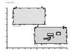


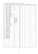


HDC-HS100P-K,PCK,PLK,E-K,EBK,EEK,EFK,EGK,EPK,GCK,GKK,GNK,GTK,SGK
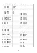
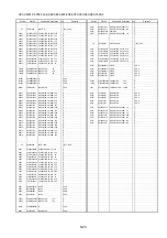
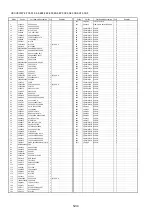
Ref.No.
Part No.
Part Name & Description
Pcs
Remarks
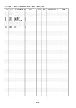
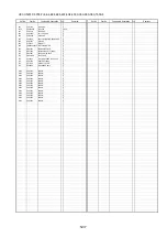
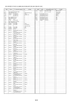
Ref.No.
Part No.
Part Name & Description
Pcs
Remarks
##
VEP03H54H
MAIN P.C.B.
1 (RTL) E.S.D.(P,PC,PL)
##
VEP20C33A
CAM FUNC OP PCB
(RTL) E.S.D.
##
VEP03H54J
MAIN P.C.B.
1 (RTL) E.S.D.(E,EF,EG)
##
VEP03H54V
MAIN P.C.B.
1 (RTL) E.S.D.(EB)
FP6631
K1KA03BA0120 CONNECTOR 3P
1
##
VEP03H54L
MAIN P.C.B.
1 (RTL) E.S.D.(EE)
##
VEP03H54S
MAIN P.C.B.
1 (RTL) E.S.D.(EP)
R6632
ERJ2GEJ473Y
M.RESISTOR CH 1/16W 47K
1
##
VEP03H54K
MAIN P.C.B.
1 (RTL) E.S.D.(GC,SG)
##
VEP03H54M
MAIN P.C.B.
1 (RTL) E.S.D.(GK)
S6631
K0H1BA000436 SWITCH
1
##
VEP03H54U
MAIN P.C.B.
1 (RTL) E.S.D.(GN)
S6632
VSS0533
SWITCH
1
##
VEP03H54X
MAIN P.C.B.
1 (RTL) E.S.D.(GT)
##
VEP01A13B
SUB P.C.B.
1 (RTL) E.S.D.
##
VEP26318A
FLASH PCB
1 (RTL) E.S.D.
##
VEP20C33A
CAM FUNC OP PCB
1 (RTL) E.S.D.
##
VEP29207A
SIDE-R P.C.B.
(RTL) E.S.D.
##
VEP29207A
SIDE-R P.C.B.
1 (RTL) E.S.D.
##
VEP24193A
MIC P.C.B.
1 (RTL) E.S.D.
C601
F3F0G4760003 E.CAPACITOR CH 4V 47U
1
##
VEP29208A
EVF B/L PCB
1 (RTL) E.S.D.
C604
F1G0J1050007 C.CAPACITOR CH 6.3V 1U
1
##
VEP26320A
MONITOR PCB
1 (RTL) E.S.D.
C605
F1G1C104A080 C.CAPACITOR CH 16V 0.1U
1
C606
F1G1C104A080 C.CAPACITOR CH 16V 0.1U
1
##
VEP26318A
FLASH PCB
(RTL) E.S.D.
C607
F1H0J225A002 C.CAPACITOR CH 6.3V 2.2U
1
C608
F1H0J225A002 C.CAPACITOR CH 6.3V 2.2U
1
C6401
F1G0J1050007 C.CAPACITOR CH 6.3V 1U
1
C609
F1G1C104A080 C.CAPACITOR CH 16V 0.1U
1
C6402
F1G1C104A080 C.CAPACITOR CH 16V 0.1U
1
C613
F1G0J1050007 C.CAPACITOR CH 6.3V 1U
1
C7001
ECJ1VB1C105K C.CAPACITOR CH 16V 1U
1
C614
F1G0J1050007 C.CAPACITOR CH 6.3V 1U
1
C7003
F1G1A104A012 C.CAPACITOR CH 10V 0.1U
1
C615
F1G1C104A080 C.CAPACITOR CH 16V 0.1U
1
C7004
F2AZZ5600001 CAPACITOR
1
C616
F1J0J1060009
C.CAPACITOR CH 6.3V 10U
1
C7005
F1K2E4730005 C.CAPACITOR 250V 0.047U
1
C6501
ECJ0EB1C103K C.CAPACITOR CH 16V 0.01U
1
C7006
F1G1A104A012 C.CAPACITOR CH 10V 0.1U
1
C6502
ECJ0EB1C103K C.CAPACITOR CH 16V 0.01U
1
C7007
ECJ1VB1H103K C.CAPACITOR CH 50V 0.01U
1
C6503
ECJ0EB1C103K C.CAPACITOR CH 16V 0.01U
1
C7010
F1K2E223A004 C.CAPACITOR 250V 0.022U
1
C6504
ECJ0EB1C103K C.CAPACITOR CH 16V 0.01U
1
C7099
F1J1C335A121 C.CAPACITOR CH 16V 3.3U
1
C6505
F1G1C104A080 C.CAPACITOR CH 16V 0.1U
1
C6506
F1G1C104A080 C.CAPACITOR CH 16V 0.1U
1
D7001
MA2S11100L
DIODE
1 E.S.D.
C6507
ECJ0EB1C103K C.CAPACITOR CH 16V 0.01U
1
D7002
B0ECGP000006 DIODE
1 E.S.D.
C6508
F3F0J226A032 T.CAPACITOR CH 6.3V 22U
1
D7003
MA2YF8000L
DIODE
1 E.S.D.
C6509
F3F0J476A032 E.CAPACITOR CH 6.3V 47U
1
D7004
B0BC30000002 DIODE
1 E.S.D.
C6511
ECJ0EB1C103K C.CAPACITOR CH 16V 0.01U
1
D7006
B0JCDD000002 DIODE
1 E.S.D.
C6512
ECJ0EB1C103K C.CAPACITOR CH 16V 0.01U
1
C6513
F1G1C104A080 C.CAPACITOR CH 16V 0.1U
1
FP6401
K1MN14BA0197 CONNECTOR 14P
1
FP6402
K1MN16BA0197 CONNECTOR 16P
1
FP601
K1MN25AA0035 CONNECTOR 25P
1
FP6501
K1MN33BA0259 CONNECTOR 33P
1
L7001
G1C560MA0024 CHIP INDUCTOR 56UH
1
IC601
C1AB00002388 IC
1 E.S.D.
PS6401
K1KA30B00077 CONNECTOR 30P
1
IC604
C0DBGGC00011 IC
1 E.S.D.
IC6501
L2ES00000017 GYROSCOPE
1 E.S.D.
Q7001
2SC6054J0L
TRANSISTOR
1 E.S.D.
Q7002
B1ABPF000009 TRANSISTOR
1 E.S.D.
L6501
G1C100KA0115 CHIP INDUCTOR 10UH
1
Q7003
2SC6054J0L
TRANSISTOR
1 E.S.D.
Q7004
XP0460100L
TRANSISTOR
1 E.S.D.
P6501
K1KA02B00304 CONNECTOR 2P
1
Q7005
B1JBLP000014 TRANSISTOR
1 E.S.D.
P6502
K1KA03BA0120 CONNECTOR 3P
1
QR6401
UNR92A5J0L
TRANSISTOR-RESISTOR
1 E.S.D.
R603
ERJ2RHD511
M.RESISTOR CH 1/16W 510
1
QR6402
UNR91A5J0L
TRANSISTOR-RESISTOR
1 E.S.D.
R604
ERJ2RHD102X RESISTOR
1
QR6403
UNR91A5J0L
TRANSISTOR-RESISTOR
1 E.S.D.
R6501
ERJ2GEJ183
M.RESISTOR CH 1/16W 18K
1
QR7001
UNR92A4J0L
TRANSISTOR-RESISTOR
1 E.S.D.
R6502
ERJ2RHD682X M.RESISTOR CH 1/16W 6.8K
1
QR7008
UNR92A4J0L
TRANSISTOR-RESISTOR
1 E.S.D.
R6503
ERJ2GEJ392
M.RESISTOR CH 1/16W 3.9K
1
R6504
ERJ2GEJ302
M.RESISTOR CH 1/16W 3K
1
R6401
ERJ2GEJ101
M.RESISTOR CH 1/16W 100
1
R6505
ERJ2GEJ103
M.RESISTOR CH 1/16W 10K
1
R6407
ERJ2GEJ331
M.RESISTOR CH 1/16W 330
1
R6506
ERJ2GEJ103
M.RESISTOR CH 1/16W 10K
1
R6408
ERJ2GEJ470
M.RESISTOR CH 1/16W 47
1
R6507
ERJ2GEJ302
M.RESISTOR CH 1/16W 3K
1
R7001
ERJ2GEJ473Y
M.RESISTOR CH 1/16W 47K
1
R6511
ERJ2GEJ103
M.RESISTOR CH 1/16W 10K
1
R7003
ERJ2GEJ470
M.RESISTOR CH 1/16W 47
1
R6512
ERJ2GEJ302
M.RESISTOR CH 1/16W 3K
1
R7004
ERJ8GEYJ105V M.RESISTOR CH 1/8W 1M
1
R6513
ERJ2GEJ392
M.RESISTOR CH 1/16W 3.9K
1
R7005
ERJ2GEJ104
M.RESISTOR CH 1/16W 100K
1
R6514
ERJ2RHD682X M.RESISTOR CH 1/16W 6.8K
1
R7006
ERJ2GEJ564
M.RESISTOR CH 1/16W 560K
1
R6515
ERJ2GEJ183
M.RESISTOR CH 1/16W 18K
1
R7007
ERJ3GEYJ104
M.RESISTOR CH 1/10W 100K
1
R6517
ERJ2GEJ102X
M.RESISTOR CH 1/16W 1K
1
R7008
ERJ2GEJ101
M.RESISTOR CH 1/16W 100
1
R6518
ERJ2GEJ473Y
M.RESISTOR CH 1/16W 47K
1
R7009
ERJ2GEJ222
M.RESISTOR CH 1/16W 2.2K
1
R7010
ERJ2GEJ222
M.RESISTOR CH 1/16W 2.2K
1
S6501
K0H1BA000436 SWITCH
1
R7011
ERJ2GEJ104
M.RESISTOR CH 1/16W 100K
1
S6502
K0H1BA000436 SWITCH
1
R7013
ERJ2GEJ822
M.RESISTOR CH 1/16W 8.2K
1
S6503
K0H1BA000436 SWITCH
1
R7014
ERJ2GEJ223
M.RESISTOR CH 1/16W 22K
1
S6504
K0H1BA000436 SWITCH
1
R7015
ERJ2GEJ560X
M.RESISTOR CH 1/16W 56
1
S6505
K0H1BA000436 SWITCH
1
R7022
ERJ2GEJ102X
M.RESISTOR CH 1/16W 1K
1
S6507
K0MZ55000009 SWITCH
1
S6508
K0H1BA000436 SWITCH
1
T7001
G5DYA0000084 SWITCHING TRANSFORMER
1
T7002
G5F1A0000021 TRIGGER COIL
1
VA6505
D4ED18R00003 VARISTORS
1
S-32
Summary of Contents for HDC-HS100P
Page 11: ...11 3 5 2 Precautions for installing HDD...
Page 14: ...14 4 Specifications...
Page 15: ...15...
Page 16: ...16 5 Location of Controls and Components...
Page 17: ...17...
Page 18: ...18...
Page 19: ...19...
Page 20: ...20...
Page 28: ...28 8 Disassembly and Assembly Instructions 8 1 Disassembly Flow Chart 8 2 PCB Location...
Page 32: ...32 Fig D5 8 3 4 Removal of the HDD Unit Fig D6...
Page 33: ...33 8 3 5 Removal of the Top Case Unit Fig D7 8 3 6 Removal of the Front Case Unit Fig D8...
Page 34: ...34 8 3 7 Removal of the Battery Case Unit Fig D9 8 3 8 Removal of the Lens Unit Fig D10...
Page 36: ...36 8 3 12 Removal of the Flash P C B Fig D14 Fig D15...
Page 38: ...38 Fig D20 8 3 16 Removal of the Monitor P C B Fig D21 Fig D22...
Page 39: ...39 8 3 17 Removal of the LCD Fig D23 8 3 18 Removal of the Mic P C B Fig D24...
Page 40: ...40 8 3 19 Removal of the Barrier Motor Unit and MF Unit Fig D25 Fig D26...
Page 41: ...41 8 3 20 Removal of the Mic Mic Damper Fig D27 8 3 21 Removal of the Power FPC Unit Fig D28...
Page 45: ...45 Fig D39 8 3 30 Removal of the IRIS Unit Fig D40 Fig D41...
Page 79: ...S 30...
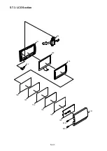
Page 90: ...S7 3 LCD Section S 41 158 157 154 155 156 153 B151 B152 151 159 160 152 161 162...


