


49
10 Factory Setting
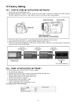
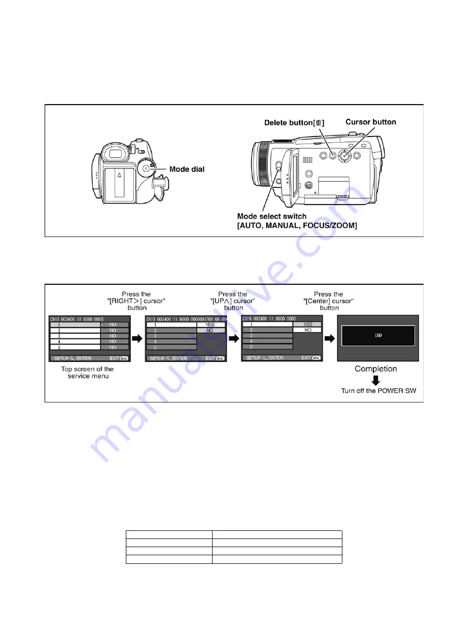
10.1. HOW TO TURN ON THE FACTORY SETTINGS?
1. Set the mode dial “HDD Recording” mode.
2. While keep pressing the “[LEFT<] of cursor” button and “delete” button, hold down the Mode Select Switch towards to
“[FOCUS]” position for more than 3 seconds until the top screen of the Service Menu being displayed.
3. Under the condition of the Item No.”1” is yellow high lighted, press the “[RIGHT>] of cursor“ button.
4. By pressing the “[UP ^] of cursor” button, then press the “[center] of cursor” button.
5. After few seconds “END” is displayed on LCD monitor. Cutting of battery connection or AC power supply connection as a
completion of the “FACTORY SETTINGS”.
10.2. WHAT IS THE FACTORY SETTINGS?
The factory settings clean up and/or refresh the following settings.
1. The OSD MENU setting data.
2. Deletion only for all scene files in a card and format of the MPEG2 file system area.
3. Reset the folder number and file number of still pictures.
(Setting the folder number is 100, and file number is 0.)
4. Clear the mechanism lock information.
5. Clear the service mode information contents.
6. Confirm the data area of HDD is cleared.
(When recorded data in HDD, "error display" is done)
The setting position of factory settings:
Name
Setting position
Mode select switch
AUTO
Mode dial
OFF
LCD/EVF select switch
LCD
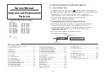
Summary of Contents for HDC-HS100P
Page 11: ...11 3 5 2 Precautions for installing HDD...
Page 14: ...14 4 Specifications...
Page 15: ...15...
Page 16: ...16 5 Location of Controls and Components...
Page 17: ...17...
Page 18: ...18...
Page 19: ...19...
Page 20: ...20...
Page 28: ...28 8 Disassembly and Assembly Instructions 8 1 Disassembly Flow Chart 8 2 PCB Location...
Page 32: ...32 Fig D5 8 3 4 Removal of the HDD Unit Fig D6...
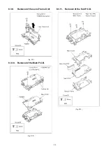
Page 33: ...33 8 3 5 Removal of the Top Case Unit Fig D7 8 3 6 Removal of the Front Case Unit Fig D8...
Page 34: ...34 8 3 7 Removal of the Battery Case Unit Fig D9 8 3 8 Removal of the Lens Unit Fig D10...
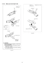
Page 36: ...36 8 3 12 Removal of the Flash P C B Fig D14 Fig D15...
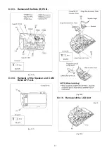
Page 38: ...38 Fig D20 8 3 16 Removal of the Monitor P C B Fig D21 Fig D22...
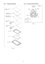
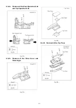
Page 39: ...39 8 3 17 Removal of the LCD Fig D23 8 3 18 Removal of the Mic P C B Fig D24...
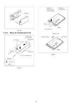
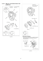
Page 40: ...40 8 3 19 Removal of the Barrier Motor Unit and MF Unit Fig D25 Fig D26...
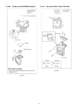
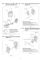
Page 41: ...41 8 3 20 Removal of the Mic Mic Damper Fig D27 8 3 21 Removal of the Power FPC Unit Fig D28...
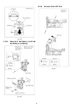
Page 45: ...45 Fig D39 8 3 30 Removal of the IRIS Unit Fig D40 Fig D41...
Page 79: ...S 30...
Page 90: ...S7 3 LCD Section S 41 158 157 154 155 156 153 B151 B152 151 159 160 152 161 162...


