


29
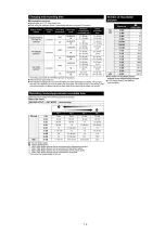
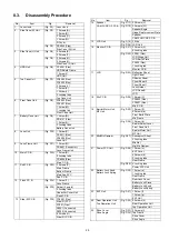
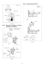
8.3.
Disassembly Procedure
No.
Item
Fig
Removal
1
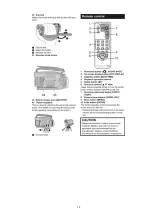
Lens Hood
Lens Hood
2
Side Case (R) Unit
7 Screws (A)
1 Screw (B)
3 Screws (C)
1 Screw (D)
R Cover
PS6003 (Flex)
Side Case (R) Unit
3
Side Case (L) Unit
2 Screws (E)
2 Screws (F)
2 Screws (G)
2 Screws (H)
Side Case (L) Unit
4
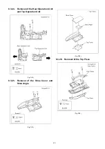
HDD Unit.
PP6001 (Flex)
HDD Shield Frame
1 Screw (i)
HDD Unit
5
Top Case Unit
FP6004 (Flex)
FP6402 (Flex)
2 Screws (J)
1 Screw (K)
1 Screw (L)
2 Locking tabs
Top Case Unit
6
Front Case Unit
FP6003 (Flex)
FP6401 (Flex)
1 Screw (M)
1 Locking tab
Front Case Unit
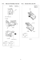
7
Battery Case Unit
1 Screw (N)
PS6101 (Flex)
1 Screw (O)
2 Locking tabs
Battery Case Unit
8
Lens Unit
(Fig. D10) 1 Screw (P)
PS6011 (Flex)
FP6002 (Flex)
Lens Unit
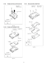
9
Lens Frame Unit
1 Screw (Q)
PS6401 (Connector)
Lens Frame Unit
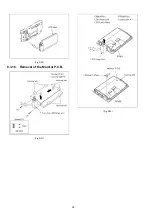
10
Main P.C.B.
(Fig. D12) 1 Screw (R)
2 Locking tabs
PS6004 (Flex)
Main P.C.B.
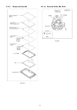
11
Sub P.C.B.
(Fig. D13) 3 Screws (S)
Main Frame
Bottom Frame
Main-Sub FPC
Sub P.C.B.
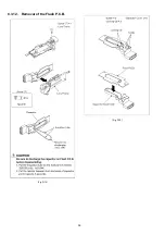
12
Flash P.C.B.
(Fig. D14) 1 Screw (T)
Lens Frame
(Fig. D15) Solder (3 points)
2 Locking tabs
Capacitor Cover Unit
Flash P.C.B.
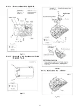
13
Side (R) P.C.B.
(Fig. D16) FP6501 (Flex)
Side (R) FPC
FP601 (Flex)
P6501 (Connector)
P6502 (Connector)
6 Screws (U)
Side (R) P.C.B.
14
Speaker
CAM FUNC OP P.C.B.
(Fig. D17) 2 Screws (V)
(Fig. D18) 2 Screws (W)
Speaker Angle
Hinge Reinforcement Plate
Speaker
CAM FUNC OP P.C.B.
15
LCD Unit
(Fig. D19) 2 Ribs
(Fig. D20) LCD Unit
16
Monitor P.C.B.
(Fig. D21) 2 Screws (X)
6 Locking tabs
(Fig. D22) FP901 (Flex)
LCD Hinge Unit
LCD Earth Plate
FP902 (Flex)
1 Locking tab
Monitor P.C.B.
17
LCD
(Fig. D23) Reflection Sheet
Light Panel
Diffusion Sheet
Prism Sheet 2
Prism Sheet 1
Lens Holder
LCD Case B
LCD
18
Mic P.C.B.
(Fig. D24) 1 Screw (Y)
FP4803 (Flex)
FP4801 (Flex)
Mic P.C.B.
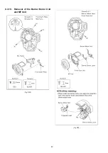
19
Barrier Motor Unit
MF Unit
(Fig. D25) 1 Screw (Z)
4 Screws (a)
Front Earth Plate
Mic Frame
(Fig. D26) 1 Screw (b)
Barrier Select Lever
Front Case Unit
Barrier Motor Unit
MF Unit
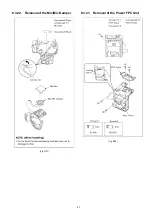
20
Mic/Mic Damper
(Fig. D27) Soundproof Sheet
3 Locking tabs
Mic Net
Mic/Mic Damper
21
Power FPC Unit
(Fig. D28) 1 Screw (c)
EVF Cover
4 Screws (d)
2 Locking tabs
Rear Frame
(Fig. D29) 4 Locking tabs
Power FPC Unit
22
Battery Lock Knob
Battery Lock Spring
(Fig. D30) 1 Screw (e)
1 Locking tab
Rear Frame
Rear Jack Cover
Battery Lock Piece
Battery Lock Knob
Battery Lock Spring
23
EVF Unit
(Fig. D31) 1 Screw (f)
1 Screw (g)
EVF Unit
24
Rear Operation Unit
Top Operation Unit
(Fig. D32) 2 Screws (h)
Rear Operation Unit
Top Operation Unit
25
Shoe Cover
Shoe Angle
(Fig. D33) 3 Screws (i)
(Fig. D34) Top Frame
Shoe Cover
Shoe Angle
No.
Item
Fig
Removal
Summary of Contents for HDC-HS100P
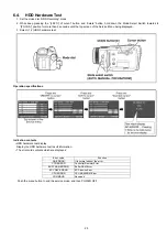
Page 11: ...11 3 5 2 Precautions for installing HDD...
Page 14: ...14 4 Specifications...
Page 15: ...15...
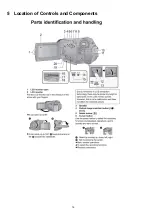
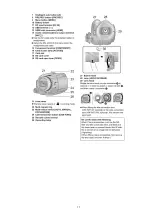
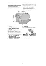
Page 16: ...16 5 Location of Controls and Components...
Page 17: ...17...
Page 18: ...18...
Page 19: ...19...
Page 20: ...20...
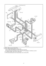
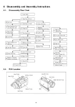
Page 28: ...28 8 Disassembly and Assembly Instructions 8 1 Disassembly Flow Chart 8 2 PCB Location...
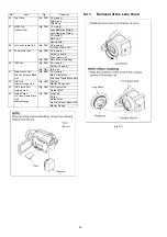
Page 32: ...32 Fig D5 8 3 4 Removal of the HDD Unit Fig D6...
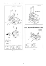
Page 33: ...33 8 3 5 Removal of the Top Case Unit Fig D7 8 3 6 Removal of the Front Case Unit Fig D8...
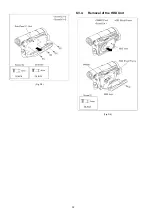
Page 34: ...34 8 3 7 Removal of the Battery Case Unit Fig D9 8 3 8 Removal of the Lens Unit Fig D10...
Page 36: ...36 8 3 12 Removal of the Flash P C B Fig D14 Fig D15...
Page 38: ...38 Fig D20 8 3 16 Removal of the Monitor P C B Fig D21 Fig D22...
Page 39: ...39 8 3 17 Removal of the LCD Fig D23 8 3 18 Removal of the Mic P C B Fig D24...
Page 40: ...40 8 3 19 Removal of the Barrier Motor Unit and MF Unit Fig D25 Fig D26...
Page 41: ...41 8 3 20 Removal of the Mic Mic Damper Fig D27 8 3 21 Removal of the Power FPC Unit Fig D28...
Page 45: ...45 Fig D39 8 3 30 Removal of the IRIS Unit Fig D40 Fig D41...
Page 79: ...S 30...
Page 90: ...S7 3 LCD Section S 41 158 157 154 155 156 153 B151 B152 151 159 160 152 161 162...


