55
9.1.1.
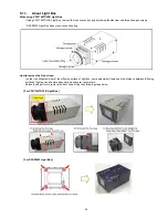
About Light Box
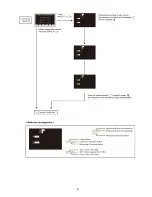
When using VFK1164TDVLB Light Box
If using VFK1164TDVLB Light Box, remove the lens connection ring by loosing thumbscrew and three hexagon screws.
* RFKZ0523 Light Box has no lens connection ring.
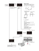
How to remove the Front Hood
In order to utilize maximum of the diffusing surface of light box, some adjustment items need the distance between diffusing
surface of light box and camera body becomes several cent-meters.
Before the adjustments, remove the front hood of light box following steps below.
[ For VFK1164TDVLB Light Box ]
[ For RFKZ0523 Light Box ]
Summary of Contents for HC-V750EB
Page 12: ...12 ...
Page 13: ...13 ...
Page 14: ...14 ...
Page 15: ...15 ...
Page 16: ...16 ...
Page 18: ...18 ...
Page 19: ...19 ...
Page 20: ...20 ...
Page 21: ...21 ...
Page 31: ...31 8 2 PCB Location ...
Page 34: ...34 8 3 1 Removal of the Side Case L Unit Fig D1 Fig D2 ...
Page 35: ...35 Fig D3 8 3 2 Removal of the Top Case Top Operation Fig D4 ...
Page 36: ...36 Fig D5 Fig D6 ...
Page 37: ...37 8 3 3 Removal of the Front Case Unit Fig D7 Fig D8 ...
Page 39: ...39 Fig D12 Fig D13 ...
Page 41: ...41 Fig D16 Fig D17 8 3 9 HC W850M V750M only Removal of the ESD P C B Unit Fig D18 ...
Page 42: ...42 8 3 10 Removal of the BR Frame Unit Speaker LCD Unit Fig D19 Fig D20 ...
Page 44: ...44 Fig D24 8 3 13 HC V750 V757 V750M V730 Removal of the LCD Hinge Unit Fig D25 ...
Page 45: ...45 Fig D26 8 3 14 Removal of the Monitor P C B LGP Unit LCD Fig D27 ...
Page 46: ...46 Fig D28 8 3 15 Removal of the Mic P C B Fig D29 ...
Page 47: ...47 8 3 16 Removal of the Front Base Barrier R Barrier F Photo Light P C B Fig D30 Fig D31 ...
Page 49: ...49 Fig D34 8 3 19 Removal of the Kurupon Unit Front P C B Fig D35 ...
Page 54: ...54 Level Shot Adjutment Chart ...
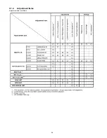
Page 56: ...56 9 1 2 Adjustment Items Adjustment item as follows ...
Page 59: ...59 ...
Page 60: ...60 ...
Page 61: ...61 ...
Page 62: ...62 ...
Page 63: ...63 ...
Page 64: ...64 ...
Page 65: ...65 ...

