background image

-12-

1. Camera Identification 

(CAMERA ID)

You can use the camera identification (CAMERA ID) to
assign a name to the camera. The camera ID consists
of up to 16 alphanumeric characters. You can select
whether to have the camera ID displayed on the moni-
tor screen or not.

Editing the CAMERA ID

1. Move the cursor to the CAMERA ID parameter.
2. Press the PAGE button. The CAMERA ID menu

appears. The cursor on the letter “A” starts blink-
ing.

3. Move the character cursor to a character you want

to edit by pressing ITEM, 

A

or 

B

.

4. After selecting the character, press the PAGE but-

ton. The selected character appears in the editing
area. (The editing cursor in the editing area moves
to the right automatically at this moment.)

5. Repeat the steps above until all characters are

edited.

Entering a blank space in the CAMERA ID

Move the character cursor to SPACE and press the
PAGE button.

Editing a specific character in the CAMERA ID

1. Move the character cursor to 

or 

, then press

the PAGE button to move the editing cursor to the
character to be edited in the editing area.

2. Move the character cursor to the character area

and select a new character.

3. Press the PAGE button to set the CAMERA ID.
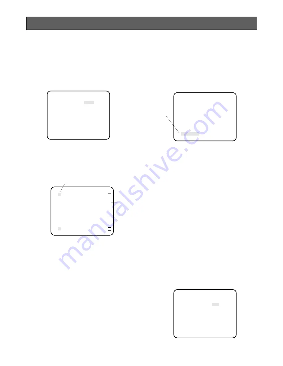
SETTING PROCEDURES

     ** SET UP **

CAMERA ID     *OFF
FLD/FRM        FLD
ELC           *OFF
SHUTTER        OFF
GAIN           AUTO
SYNC          *INT
BLACK BAL      ABC
SCENE FILE    *SCENE1

END

GP-US522

ABCDEFGHIJKLM
NOPQRSTUVWXYZ
0123456789
().,'":;&#!?=
+-*/%$ÄÜÖÆÑÅ


  SPACE

*POSI RET END RESET

................

Erasing all characters in the editing area

Move the character cursor to RESET and press the
PAGE button. All characters in the editing area disap-
pear.

Determining the display position of the CAMERA ID

1. Move the cursor to POSI, and press the PAGE but-

ton. The display shown below appears and the
CAMERA ID starts blinking.

2. Move the CAMERA ID to the desired position by

pressing 

A

B

or the ITEM button.

3. Press the PAGE button to fix the position of the

CAMERA ID. The mode returns to the previous
CAMERA ID menu.

Notes:

• The CAMERA ID stops at the edges of the

monitor screen.

• The CAMERA ID moves faster if any of 

A

B

or

the ITEM button is kept pressed for a second
or longer.

Returning to the SETUP menu

Move the cursor to RET and press the PAGE button.
The SETUP menu appears.

Displaying the CAMERA ID on the monitor screen

Move the cursor to CAMERA ID in the SETUP menu and
select ON.

2. Field/Frame Charging Mode Setting

(FLD/FRM)

You can select the charging mode from FIELD or
FRAME.

E

diting Curs

or

Character Cursor

Character
Area

Blinking

Command

Editing
Area

     ** SET UP **

CAMERA ID     *OFF
FLD/FRM        FLD
ELC           *OFF
SHUTTER        OFF
GAIN           AUTO
SYNC           INT
BLACK BAL      ABC
SCENE FILE    *SCENE1

END

Summary of Contents for GP-US522CUE

Page 1: ...Head GP US522HE GP US532HE 3 CCD Colour Camera CCU GP US522CUE Lens Purchased locally Cable Option Before attempting to connect or operate this product please read these instructions completely DEUTS...

Page 2: ...he provisions of Directive EEC 89 336 Nosotros declaramos bajo nuestra nica responsabilidad que el producto a que hace referencia esta declaraci n est conforme con las normas u otros documentos normat...

Page 3: ...ERATING CONTROLS AND THEIR FUNCTIONS 4 Camera Head 4 Camera Control Unit 4 CONNECTIONS 8 SETUP 10 1 CAMERA SETUP MENU 10 2 SETUP OPERATION 10 SETTING PROCEDURES 12 PREVENTION OF BLOOMING AND SMEAR 21...

Page 4: ...performance micro prism optical system with three 1 2 IT CCDs 2 800 lines of horizontal resolution for GP US522 and 750 lines for GP US532 3 Signal to noise ratio of 60 dB 4 Minimum scene illuminatio...

Page 5: ...the camera or the camera control unit body Use a dry cloth to clean the camera or the camera control unit when dirty In case the dirt is hard to remove use a mild deter gent and wipe gently 8 Clean t...

Page 6: ...power of this unit and the power supply for the camera head on or off 5 Power Indicator POWER This indicator lights up red when the power switch is turned on 6 Automatic Manual Gain Selector Switch GA...

Page 7: ...ction switch ATW AWC MANU is set to MANU Turn the controls clockwise to increase the red and blue signal levels and counterclockwise to decrease 11 Page Button PAGE This button is used to display the...

Page 8: ...he gen lock signal Composite Signal Black Burst Signal or Video Sync when either signal is supplied to this connec tor The gen lock signal is used for system reference Caution If the gen lock signal i...

Page 9: ...Video Output 1 0V p p 75 7 Sync SYNC Output 4 0V p p or 0 3V p p 75 8 Ground GND 9 Ground GND 26 RS 232C Connector RS 232C Pin No Signal RS 232C Ground TXD RXD DSR Ground DTR CTS RTS Ground 1 2 3 4 5...

Page 10: ...obtained locally Caution Connect to 12 V DC 11 5 V 16 V class 2 power supply only 3 Connect the power cable between the 12V DC input terminals and the 12V DC power supply unit obtained locally The ma...

Page 11: ...f the optical filter is dirty clean it with a blower brush sold for cleaning camera lenses available at your local camera store 2 Mount the C mount lens by turning it clockwise onto the lens mount of...

Page 12: ...h time this button is pressed Right Button B This button is used to move the cursor to the right Use this button to select or adjust the parameters of the selected item The parameter changes each time...

Page 13: ...er formed SET UP CAMERA ID OFF FLD FRM FLD ELC OFF SHUTTER OFF GAIN AUTO SYNC INT BLACK BAL ABC SCENE FILE SCENE1 END SET UP CAMERA ID OFF FLD FRM FLD ELC OFF SHUTTER OFF GAIN AUTO SYNC INT BLACK BAL...

Page 14: ...ID SETTING PROCEDURES SET UP CAMERA ID OFF FLD FRM FLD ELC OFF SHUTTER OFF GAIN AUTO SYNC INT BLACK BAL ABC SCENE FILE SCENE1 END GP US522 ABCDEFGHIJKLM NOPQRSTUVWXYZ 0123456789 SPACE POSI RET END RES...

Page 15: ...and select the desired detection area You can select the detection area as follows ALL All areas on the monitor screen are detected MANU Detection areas are selectable manually See below for details...

Page 16: ...appears 3 1 2 Peak and Average Weight Control PEAK AVE 1 Move the cursor to the PEAK AVE parameter The I cursor starts blinking Note A masked area will be excluded from ELC detection Masked Area WHITE...

Page 17: ...FRM FLD ELC OFF SHUTTER OFF GAIN AUTO SYNC INT BLACK BAL ABC SCENE FILE SCENE1 END SET UP CAMERA ID OFF FLD FRM FLD ELC OFF SHUTTER MANU GAIN AUTO SYNC INT BLACK BAL ABC SCENE FILE SCENE1 END SHUTTER...

Page 18: ...ustments When the cable length of the video output or the gen lock input is changed horizontal and subcarrier phase must be readjusted The VS gen lock mode has its own menu for hori zontal and subcarr...

Page 19: ...colour shift Notes When the I cursor reaches the end it jumps back to At the same time SC COARSE is incre mented by one step to enable a continuous adjust ment The reverse takes place when the I curso...

Page 20: ...This setting will not be lost even if the camera con trol unit is turned off However for best results it is recommended that the black balance adjustment be carried out when the camera has not been u...

Page 21: ...ILE 2 1 Move the cursor to the SCENE FILE parameter and select SCENE 1 2 Press the PAGE button The SCENE FILE menu appears There are 2 pages for SCENE FILE P1 and P2 On page 1 P1 you can set the follo...

Page 22: ...I cursor starts blinking 2 While observing the colour video monitor adjust the aperture level Move the I cursor to the side to make the image sharper Move the I cursor to the side to make the image so...

Page 23: ...perated carefully in the vicinity of extremely bright objects to avoid smear or blooming If the camera is aimed at the sun or very bright light such as a laser beam for a long period of time the CCD i...

Page 24: ...amma Horizontal Resolution 800 lines at centre Y signal GP US522 750 lines at centre Y signal GP US532 White Balance ATW Automatic Tracing White Balance Control AWC Automatic White Balance Control and...

Page 25: ...23 OPTIONAL ACCESSORIES Camera Cable GP CA522 4 Character Generators WJ KB30 WJ KB50...

Page 26: ...Matsushita Electric Industrial Co Ltd Central P O Box 288 Osaka 530 91 Japan N1197 1117 YWV8QA4820BN Printed in Japan N 30 Gedruckt in Japan Imprim au Japon...

Reviews: