-10-
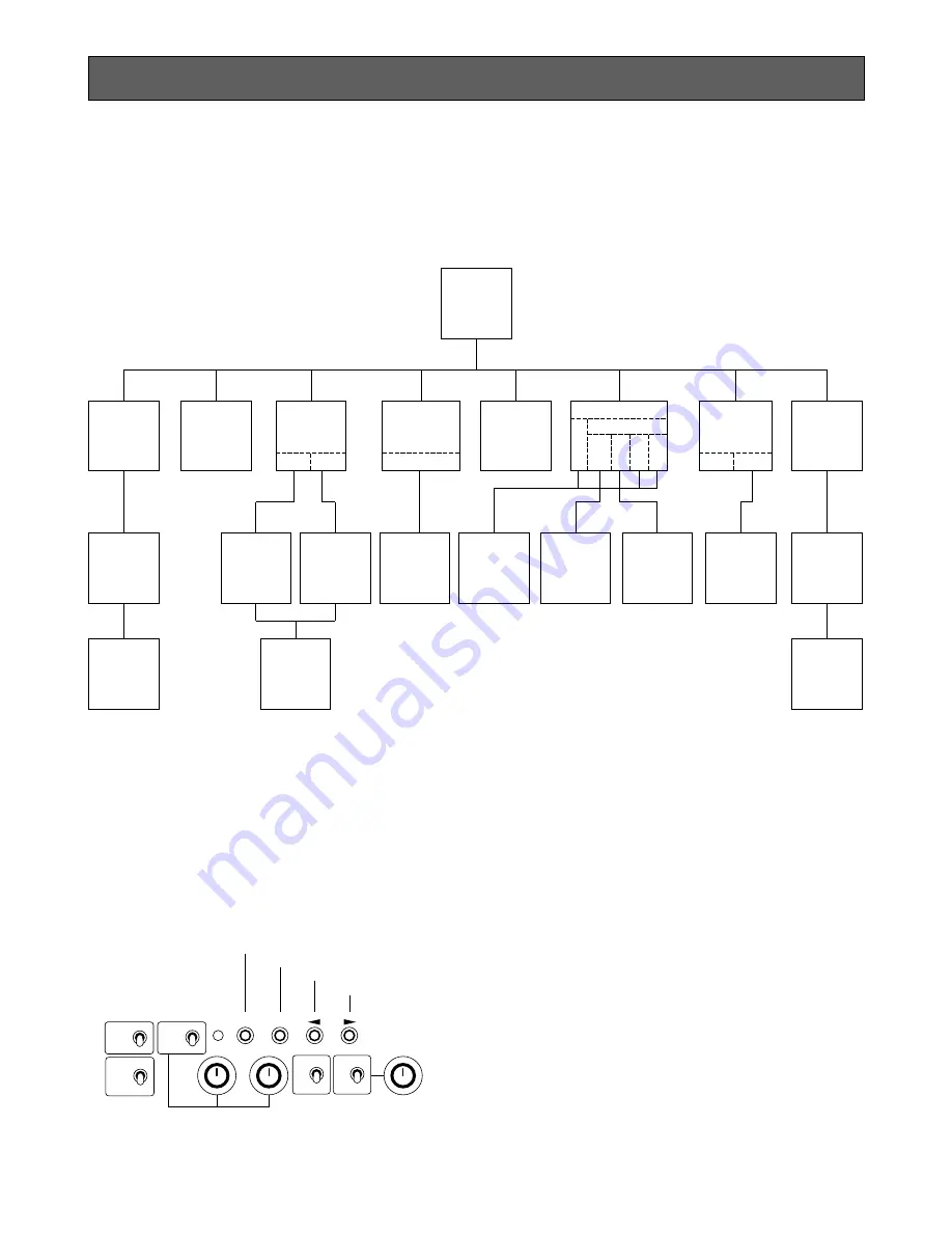
1. CAMERA SETUP MENU
This camera utilizes a user setup menu that is dis-
played on-screen.
The setup menu contains various items that form a
tree-type structure as shown below.
2. SETUP OPERATION
This camera utilizes a user setup menu (SETUP)
that is displayed on the monitor.
To set items on the SETUP menu, use the following
buttons on the front panel of the camera control
unit.
Page Button (PAGE) :
This button is used to display the SETUP menu.
Use this button to select an item.
Item Button (ITEM) :
This button is used to move the cursor downwards.
Left Button (
A
)
This button is used to move the cursor to the left.
Use this button to select or adjust the parameters
of the selected item. The parameter changes each
time this button is pressed.
Right Button(
B
)
This button is used to move the cursor to the right.
Use this button to select or adjust the parameters
of the selected item. The parameter changes each
time this button is pressed.
It is described in the following section: “2. SETUP
OPERATION”.
Note:
The SETUP menu is output from the VIDEO 1, 2
connectors, the S-VIDEO OUT connector, and
the RGB/SYNC connector.
SETUP
SETUP
Menu
Camera
ID
ON/OFF
FLD/FRM
Light
Control
(ELC)
ON OFF
Shutter
(Speed)MANU
SYNC
EXT
HD
INT VBS VS VD
VD
Gain
AUTO/MANU
Black
Balance
ABC MANU
Scene File
R-Pedestal
B-Pedestal
PAGE 1
PAGE 2
Camera
ID
Editing
Camera
ID
Display
Position
Manual
Area
Setting
ELC
Area
Peak/Ave
AGC
Area
Peak/Ave
Manual
Adjustment
RGB Sync
RGB Sync
SC-Coase
SC-Fine
RGB Sync
CAM
BAR
R
B
1
2
SCENE
ON
OFF
ELC
LEVEL
PAGE ITEM
(AWC)
(ABC)
GAIN
Page Button
Item Button
Left Button
Right Button
HIGH
ATW
MANU
LOW
OFF
AWC
GAIN


