Operation manual for Narrow-pitch connectors F4S
Panasonic Corporation
industrial.panasonic.com/ac/e/
©
Panasonic Corporation 2017
ACCTF5E-5 201704
- 7 -
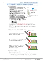
(4)
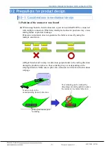
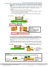
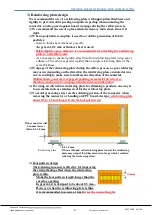
Precautions when providing a pattern and through-hole inside the prohibited
area
As shown below, the header’s post extends down to the bottomface of the molded
part, and the post extends horizontally beyond the molded part becomes the
terminal.
From this structure,pay attention to the following points.
①
When providing an uninsulated through-hole, make sure to design it so that it
does not interfere with adjacent terminals.
②
It is recommended that the patterns not be interfered in contiguous contacts.
(5)
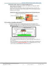
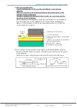
Precautions when providing an insulated through-hole in a prohibited area
As shown below, the header’s post extends down to the bottomface of the molded
part, and the post extends horizontally beyond the molded part becomes the
terminal.
If an insulated through-hole is placed in the prohibited area, the gap between the
pattern and connector terminal becomes wider, which may result in poor soldering.
①
interfering with
adjacent terminal
②
interfering with
adjacent terminal
Lead out straight to avoid
interference with adjacent terminals
Sectional view
A gap becomes
wider and increases
the risk of poor
soldering.
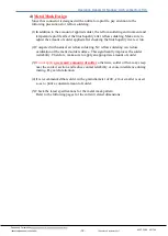
●
Key point.
We recommend that you provide a through-hole closer to the center, out of the prohibited area.
A 50-µm step
between the terminal
and molded part
A gap can be
absorbed by a step
between the molded
part and the
terminal.
Sectional view
Top view
Through-hole
prohibited area
●
Key point
When leading out a pattern
that is not insulated inside,
be
careful not to contact any
adjacent terminals.
●
If there is a through-hole in the prohibited area
post
terminal


