
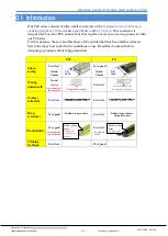

Operation manual for Narrow-pitch connectors F4S
Panasonic Corporation
industrial.panasonic.com/ac/e/
©
Panasonic Corporation 2017
ACCTF5E-5 201704
- 10 -
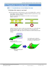
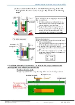
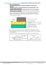
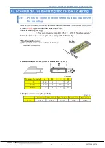
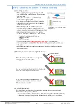
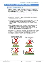
(2)
FPC board specifications
Control the thicknesses of the coverlay and adhesive to prevent poor
soldering.
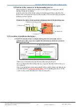
There is a clearance of about 0.05 mm between the bottom surface of the
terminal and the molded part.
Therefore, minimize the thickness of the coverlay, etc. so as to prevent the
occurrence of poor soldering.
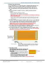
If poor soldering occurs frequently, check the actual thickness of each insulation
layer.
Generally, the coverlay thickness is set to about 30 μm, including the
adhesive. If the thickness exceeds 30 μm, design the board so as to remove the
coverlay under the connector.
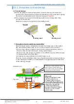
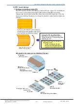
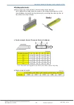
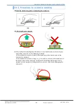
(3)This connector is often used for connecting the motherboard and FPC board. In
this case, if the FPC board is too short, a load that causes deviation will be applied
to the connector.
Make sure to create a design that provides some allowance in the FPC board.
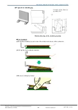
Connector
terminal
Molded part of the connector
Coverlay (polyimide)
Adhesive (epoxy adhesive recommended)
Adhesive (epoxy adhesive recommended)
Copper foil
Base material (polyimide)
Reinforcing plate + Adhesive
(epoxy adhesive recommended)
X Too long
Fixed
Connector
X Too short
Positional deviation
Motherboard
Part where FPC board is
fixed