14
6 Service Mode
6.1.
Error Code Memory Function
1.
General description
This unit is equipped with history of error code memory function, and can be memorized 32 error codes in sequence from the
latest. When the error is occurred more than 32, the oldest error is overwritten in sequence.
The error code is not memorized when the power supply is shut down forcibly (when the unit is powered on by the battery, the
battery is pulled out) because the error code is memorized to FLASH ROM when the unit is powered off.
2.
How to display
The error code can be displayed by the following procedure:
Before perform the error code memory function, connect the AC adaptor or insert the battery, and insert the SD card.
•
1. The temporary cancellation of factory setting:
Set the mode dial to “[ Normal picture mode ] (Red camera mark)”.
While keep pressing [ Optical Image Stabilizer Button ] and “[ UP ] of Cross key” simultaneously, turn the Power on.
•
2. The display of error code:
Press [ Optical Image Stabilizer Button ], [ MENU ] and “[ LEFT ] of Cross key” simultaneously with the step 1 condition.
The display is changed as shown below when the above buttons is pressed simultaneously.
Normal display
→
Error code display
→
Operation history display
→
Normal display
→
.....
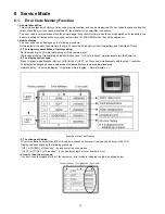
Example of Error Code Display
•
3. The change of display:
The error code can be memorized 32 error codes in sequence, however it is displayed 5 errors on the LCD.
Display can be changed by the following procedure:
“[ UP ] or [ DOWN ] of Cross key” : It can be scroll up or down one.
“[ LEFT ] or [ RIGHT ] of Cross key” : It can be display last 5 error or another 5 error.
•
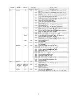
4. How to read the error code:
One error code is displayed for 8 bit, the contents of error codes is indicated the table as shown below.
Summary of Contents for DMC-FX07EB
Page 8: ...8 NOTE Above caution is applicable for a battery pack which is for DMC FX07 series as well ...
Page 12: ...12 4 Specifications ...
Page 13: ...13 5 Location of Controls and Components ...
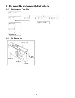
Page 20: ...20 8 Disassembly and Assembly Instructions 8 1 Disassembly Flow Chart 8 2 PCB Location ...
Page 28: ...28 ...


