13
•
Step 4. Display the Initial Settings:
While pressing [ MENU/SET ] button and “[ RIGHT ] of Cursor buttons” simultaneously, turn the power off.
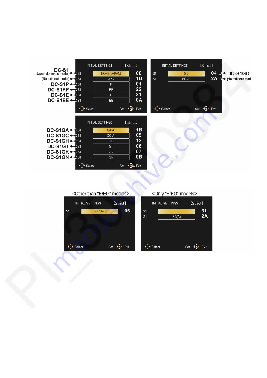
The “Initial Settings” menu is displayed.
[ CASE 1. After replacing the Main P.C.B. and/or Flash-ROM ]
When Main P.C.B. has just been replaced, 14 model suffixes are displayed as follows. (three pages in total)
[CASE 2. Other than “After replacing the Main P.C.B. and/or Flash-ROM”]
Summary of Contents for DC-S1P
Page 17: ...17 ...
Page 18: ...18 ...
Page 19: ...19 ...
Page 20: ...20 ...
Page 21: ...21 ...
Page 22: ...22 ...
Page 29: ...29 ...
Page 32: ...32 ...
Page 33: ...33 ...
Page 36: ...36 ...
Page 40: ...40 9 2 P C B Location ...
Page 43: ...43 Fig D2 Fig D3 ...
Page 44: ...44 Fig D4 Fig D5 ...
Page 45: ...45 Fig D6 Fig D7 ...
Page 46: ...46 Fig D8 Fig D9 9 3 3 Removal of the Top 1 Unit Fig D10 ...
Page 47: ...47 Fig D11 Fig D12 9 3 4 Removal of the Main P C B Fig D13 ...
Page 48: ...48 Fig D14 Fig D15 9 3 5 Removal of the EXT MIC HP P C B Fig D16 ...
Page 50: ...50 Fig D20 Fig D21 9 3 9 Removal of the Battery Case Unit Fig D22 ...
Page 51: ...51 Fig D23 9 3 10 Removal of the WIFI BT P C B Fig D24 ...
Page 54: ...54 Fig D29 9 3 15 Removal of the SD Door Unit Fig D30 ...
Page 56: ...56 9 3 18 Removal of the Rear IF P C B Fig D34 9 3 19 Removal of the LCD Unit Fig D35 ...
Page 58: ...58 9 3 23 Removal of the Image Sensor Unit Fig D39 Fig D40 ...


