background image

14

Troubleshooting

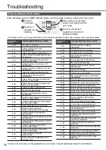
How to retrieve error codes

If the unit stops and the TIMER indicator blinks, use the remote control to retrieve the error code.

ON

OFF

SET

TIMER

CANCEL

ON

OFF

SET

TIMER

CANCEL

Press for 
5 seconds

Press for 5 
seconds to quit 
checking

Press until you hear beep 
sound, then write down the 
error code

Turn the unit off and 
reveal the error code to 
authorised dealer

2

1

3

4

• For certain errors, you may restart the unit for limited operation if there are 4 beeps when operation starts.

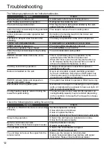
Diagnostic 

display

Abnormality/Protection control

H 00

No memory of failure

H 11

Indoor/outdoor abnormal 

communication

H 12

Indoor unit capacity unmatched

H 14

Indoor intake air temperature sensor 

abnormality

H 15

Outdoor compressor temperature 

sensor abnormality

H 16

Outdoor current transformer (CT) 

abnormality

H 17

Outdoor suction temperature sensor 

abnormality

H 19

Indoor fan motor mechanism lock

H 21

Indoor 

fl

 oat switch operation 

abnormality

H 23

Indoor heat exchanger temperature 

sensor 1 abnormality

H 24

Indoor heat exchanger temperature 

sensor 2 abnormality

H 25

Indoor ion device abnormality

H 26

Minus ION abnormality

H 27

Outdoor air temperature sensor 

abnormality

H 28

Outdoor heat exchanger temperature 

sensor 1 abnormality

H 30

Outdoor discharge pipe temperature 

sensor abnormality

H 31

Abnormal swimming pool sensor

H 32

Outdoor heat exchanger

temperature sensor 2 abnormality

H 33

Indoor/outdoor misconnection 

abnormality

H 34

Outdoor heat sink temperature sensor 

abnormality

H 35

Indoor/outdoor water adverse current 

abnormality

H 36

Outdoor gas pipe temperature

sensor abnormality

H 37

Outdoor liquid pipe temperature

sensor abnormality

H 38

Indoor/outdoor mismatch 

(brand code)

H 39

Abnormal indoor operating unit or

standby units

Diagnostic 

display

Abnormality/Protection control

H 41

Abnormal wiring or piping

connection

H 50

Ventilation fan motor locked

H 51

Ventilation fan motor locked

H 52

Left-right limit switch 

fi

 xing 

abnormality

H 58

Indoor gas sensor abnormality

H 59

Eco sensor abnormality

H 64

Outdoor high pressure sensor

abnormality

H 67

nanoe abnormality

H 70

Light sensor abnormality

H 71

DC cooling fan inside control board 

abnormality

H 72

Abnormality tank temperature sensor

H 97

Outdoor fan motor mechanism lock

H 98

Indoor high pressure protection

H 99

Indoor operating unit freeze protection

F 11

4-way valve switching abnormality

F 16

Total running current protection

F 17

Indoor standby units freezing

abnormality

F 18

Dry circuit blocked abnormality

F 87

Control box overheat protection

F 90

Power factor correction (PFC)

circuit protection

F 91

Refrigeration cycle abnormality

F 93

Outdoor compressor abnormal 

revolution

F 94

Compressor discharge pressure

overshoot protection

F 95

Outdoor cooling high pressure 

protection

F 96

Power transistor module overheating 

protection

F 97

Compressor overheating protection

F 98

Total running current protection

F 99

Outdoor direct current (DC) peak 

detection

* Some error code may not be applicable to your model. Consult authorised dealer for clari

fi

 cation.

Summary of Contents for CS-LZ25TKE

Page 1: ... av installatören före installationen Bruksanvisninger Klimaanlegg 30 43 Les bruksanvisningen nøye før du bruker denne enheten og oppbevar den for fremtidig bruk Installatøren bør oppbevare og lese de medfølgende installasjonsinstruksene før installasjon Fjernkontrollen skal pakkes inn i innendørsenheten og fjernes av installatøren før installasjon Käyttöohjeet Ilmastointilaite 44 57 Lue nämä käyt...

Page 2: ...and set the time Press and hold for approximately 5 seconds to show time in 12 hour am pm or 24 hour indication 2 Confirm SET Use remote control within 8 m from the remote control receiver of the indoor unit AIR CONDITIONER ON OFF SET TIMER CANCEL TEMP FAN SPEED i f SET TEMP 2 control receiver of the indoor unit AIR SWING AIR SWING OFF ON MODE AIR CONDITIONER ON OFF TIMER CANCEL FAN SPEED AIR SWIN...

Page 3: ...k you for purchasing Panasonic Air Conditioner WARNING This symbol shows that this equipment uses a flammable refrigerant If the refrigerant is leaked together with an external ignition source there is a possibility of ignition CAUTION This symbol shows that the Operation Instructions should be read carefully CAUTION This symbol shows that there is information included in the Operation Instruction...

Page 4: ...r lack of experience and knowledge if they have been given supervision or instruction concerning use of the appliance in a safe way and understand the hazards involved Children shall not play with the appliance Cleaning and user maintenance shall not be made by children without supervision Please consult authorised dealer or specialist to clean the internal parts repair install remove and reinstal...

Page 5: ...rcuit Breaker ELCB or Residual Current Device RCD to prevent electric shock or fire To prevent overheating fire or electric shock Insert the power plug properly Dust on the power plug should be periodically wiped with a dry cloth Stop using the product if any abnormality failure occurs and disconnect the power plug or turn off the power switch and breaker Risk of smoke fire electric shock Examples...

Page 6: ...ing and flare nuts on the outdoor unit side The R32 flare nut and pipe on the outdoor unit side can also be used for a R410A model Models that use refrigerant R32 and R410A have a different charging port thread diameter to prevent erroneous charging with refrigerant R22 and for safety Therefore check beforehand The charging port thread diameter for R32 and R410A is 12 7 mm 1 2 inch Be extra carefu...

Page 7: ...nit to avoid injury Do not place a vase or water container on the unit Water may enter the unit and degrade the insulation This may cause an electric shock Do not open window or door for long time during operation it may lead to inefficient power usage and uncomfortable temperature changes Prevent water leakage by ensuring drainage pipe is Connected properly Kept clear of gutters and containers or...

Page 8: ...he indoor fan speed is automatically adjusted according to the operation mode To have low noise priority operation select the lowest fan speed To adjust fan speed AUTO FAN To switch between powerful quiet Do not adjust the flap by hand Do not insert finger into the air flow outlet to prevent injury Maintain indoor temperature at 8 15 C Fan switches to high fan speed automatically This operation ov...

Page 9: ...To cancel ON or OFF timer press or to select respective or then press If timer is cancelled manually or due to power failure you can restore the timer again by pressing or to select respective or then press SET The nearest timer setting will be displayed and will activate in sequence Timer operation is based on the clock set in the remote control and repeats daily once set For clock setting please...

Page 10: ...perature range may save energy HEAT 20 0 C 24 0 C 68 F 75 F COOL 26 0 C 28 0 C 79 F 82 F Air flow direction In COOL DRY mode If AUTO is set the flap swings left right and up down automatically In HEAT mode If AUTO is set the horizontal flap is fixed at the predetermined position The vertical flap swings left right after the temperature rises Auto restart control If power is resumed after a power f...

Page 11: ...oid damage to the filter surface Dry the filters thoroughly under shade away from fire or direct sunlight Replace any damaged filters Insert into the unit Attach air filter Remove air filter Front panel Wash gently and dry Remove the front panel Close it securely Raise Pull out 1 2 Insert and push in at both side 1 Press both ends of the front panel 3 Close down 2 Indoor unit Air Purifying Filter ...

Page 12: ...ccumulated on the wall Due to air circulation or static electricity generated by the air conditioner Some types of wall paper may collect dusts easily recommended to clean the area around the air conditioner frequently POWER indicator blinks and stops when operate COOL DRY mode The system has locked to operate in HEAT mode only Discoloration of some plastic parts Discoloration is subject to materi...

Page 13: ...nlet and outlet vents Use Auto OFF ON button to select COOL HEAT operation After 15 minutes of operation it is normal to have the following temperature difference between the air inlet and outlet vents COOL 8 C 14 4 F HEAT 14 C 25 2 F The units are not going to be used for a long period of time Activate HEAT mode for 2 3 hours to remove moisture left in the internal parts thoroughly to prevent mou...

Page 14: ...nection abnormality H 34 Outdoor heat sink temperature sensor abnormality H 35 Indoor outdoor water adverse current abnormality H 36 Outdoor gas pipe temperature sensor abnormality H 37 Outdoor liquid pipe temperature sensor abnormality H 38 Indoor outdoor mismatch brand code H 39 Abnormal indoor operating unit or standby units Diagnostic display Abnormality Protection control H 41 Abnormal wiring...

Page 15: ...ling For more information about collection and recycling of old products and batteries please contact your local municipality your waste disposal service or the point of sale where you purchased the items Penalties may be applicable for incorrect disposal of this waste in accordance with national legislation Pb For business users in the European Union If you wish to discard electrical and electron...

Reviews: