


3 Product Specifications
Unit
CS-HE9DKE
CU-HE9DKE
Cooling Capacity
kW
kcal/h
BTU/h
2.60 (0.60 - 3.00)
2,240 (520 - 2,580)
8,870 (2,050 - 10,200)
Heating Capacity
kW
kcal/h
BTU/h
3.60 (0.60 - 6.50)
3,100 (520 - 5,590)
12,300 (2,050 - 22,080)
Moisture Removal
l/h
Pint/h
1.5
(3.2)
Power Source
Phase
V
Cycle
Single
230/240
50
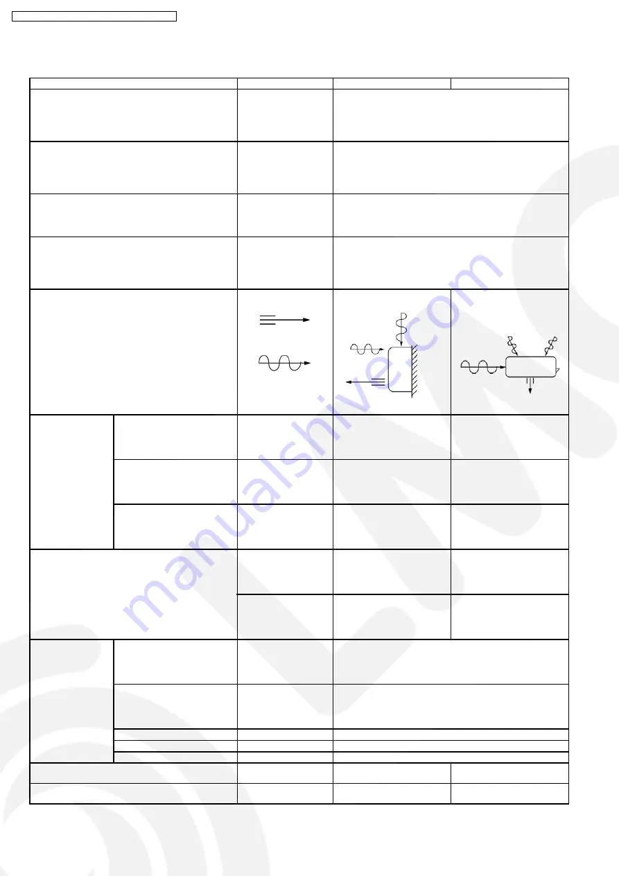
Airflow Method
OUTLET
INTAKE
SIDE VIEW
TOP VIEW
Air Volume
Indoor Air (Lo)
m
3
/min (cfm)
Cooling; 5.2 (180)
—
Heating; 6.3 (220)
Indoor Air (Me)
m
3
/min (cfm)
Cooling; 7.9 (280)
—
Heating; 8.8 (310)
Indoor Air (Hi)
m
3
/min (cfm)
Cooling; 10.5 (370)
Cooling; 23.8 (840)
Heating; 11.5 (410)
Heating; 23.1 (820)
dB (A)
Cooling; High 39, Low 26
Cooling; 46
Heating; High 40, Low 27
Heating; 47
Noise Level
Power level dB
Cooling; High 50
Cooling; High 59
Heating; High 51
Heating; High 60
Electrical Data
Input
W
Cooling; 510 (120 - 700)
Heating; 690 (115 - 1,720)
Running Current
A
Cooling; 2.6
Heating; 3.5
EER
W/W (kcal/hw), BTU/hw
Cooling; 5.10 (4.39), 17.4
COP
W/W (kcal/hw), BTU/hw
Heating; 5.22 (4.49), 17.8
Starting Current
A
3.6
Piping Connection Port
(Flare piping)
inch
inch
G ; Half Union 3/8”
L ; Half Union 1/4”
G ; 3-way valve 3/8”
L ; 2-way valve 1/4”
Pipe Size
(Flare piping)
inch
inch
G (gas side) ; 3/8”
L (liquid side) ; 1/4”
G (gas side) ; 3/8”
L (liquid side) ; 1/4”
6
CS-HE9DKE CU-HE9DKE / CS-HE12DKE CU-HE12DKE
Summary of Contents for CS-HE9DKE
Page 3: ...2 Functions 2 1 Remote Control 3 CS HE9DKE CU HE9DKE CS HE12DKE CU HE12DKE...
Page 4: ...2 2 Indoor Unit 4 CS HE9DKE CU HE9DKE CS HE12DKE CU HE12DKE...
Page 5: ...2 3 Outdoor unit 5 CS HE9DKE CU HE9DKE CS HE12DKE CU HE12DKE...
Page 10: ...4 Dimensions 4 1 Indoor Unit Remote Control 10 CS HE9DKE CU HE9DKE CS HE12DKE CU HE12DKE...
Page 11: ...4 2 Outdoor Unit 11 CS HE9DKE CU HE9DKE CS HE12DKE CU HE12DKE...
Page 12: ...5 Refrigeration Cycle Diagram 12 CS HE9DKE CU HE9DKE CS HE12DKE CU HE12DKE...
Page 13: ...6 Block Diagram 13 CS HE9DKE CU HE9DKE CS HE12DKE CU HE12DKE...
Page 14: ...7 1 Indoor Unit 7 Wiring Diagram 14 CS HE9DKE CU HE9DKE CS HE12DKE CU HE12DKE...
Page 15: ...7 2 Outdoor Unit 15 CS HE9DKE CU HE9DKE CS HE12DKE CU HE12DKE...
Page 17: ...17 CS HE9DKE CU HE9DKE CS HE12DKE CU HE12DKE...
Page 18: ...8 2 Outdoor Unit 18 CS HE9DKE CU HE9DKE CS HE12DKE CU HE12DKE...
Page 19: ...19 CS HE9DKE CU HE9DKE CS HE12DKE CU HE12DKE...
Page 39: ...10 Operating Instructions 39 CS HE9DKE CU HE9DKE CS HE12DKE CU HE12DKE...
Page 40: ...40 CS HE9DKE CU HE9DKE CS HE12DKE CU HE12DKE...
Page 41: ...41 CS HE9DKE CU HE9DKE CS HE12DKE CU HE12DKE...
Page 42: ...42 CS HE9DKE CU HE9DKE CS HE12DKE CU HE12DKE...
Page 43: ...43 CS HE9DKE CU HE9DKE CS HE12DKE CU HE12DKE...
Page 44: ...44 CS HE9DKE CU HE9DKE CS HE12DKE CU HE12DKE...
Page 82: ...CS HE12DKE CU HE12DKE 82 CS HE9DKE CU HE9DKE CS HE12DKE CU HE12DKE...