7
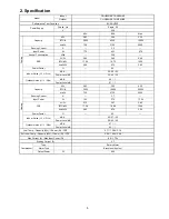
Indoor
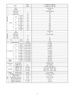
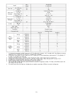
CS-HE9NKE CS-AE9NKE
Model
Outdoor
CU-HE9NKE CU-AE9NKE
Inner Diameter
mm
16
Drain Hose
Length mm
650
Fin Material
Aluminium (Pre Coat)
Fin Type
Slit Fin
Row × Stage × FPI
2 × 17 × 21
Indoor Heat
Exchanger
Size (W × H × L)
mm
636.5 × 357 × 25.4
Fin Material
Aluminium
Fin Type
Corrugate Fin
Row × Stage × FPI
2 × 28 × 17
Outdoor Heat
Exchanger
Size (W × H × L)
mm
36.4 × 588 × 856.3:827.7
Material
Polypropelene
Air Filter
Type
One-touch
Power Supply
Indoor
Power Supply Cord
A
Nil
Thermostat
Electronic
Control
Protection Device
Electronic Control
Dry Bulb
Wet Bulb
Maximum 32
23
Cooling
Minimum 16
11
Maximum 30
—
Heating
Minimum 16
—
Maximum 10
—
Indoor
Operation
Range
+8/10°C
HEAT
Minimum 8
—
Maximum 43
26
Cooling
Minimum 16
11
Maximum 24
18
Heating
Minimum -15
—
Maximum —
—
Outdoor
Operation
Range
+8/10°C
HEAT
Minimum -15
—
1.
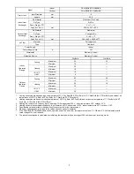
Cooling capacities are based on indoor temperature of 27°C Dry Bulb (80.6°F Dry Bulb), 19.0°C Wet Bulb (66.2°F Wet Bulb) and outdoor air
temperature of 35°C Dry Bulb (95°F Dry Bulb), 24°C Wet Bulb (75.2°F Wet Bulb)
2.
Heating capacities are based on indoor temperature of 20°C Dry Bulb (68°F Dry Bulb) and outdoor air temperature of 7°C Dry Bulb (44.6°F
Dry Bulb), 6°C Wet Bulb (42.8°F Wet Bulb)
3.
Heating low temperature capacity, Input Power and COP measured at 230 V, indoor temperature 20°C, outdoor 2/1°C.
4.
Heating extreme low temperature capacity, Input Power and COP measured at 230 V, indoor temperature 20°C, outdoor -7/-8°C.
5.
Specifications are subjected to change without prior notice for further improvement.
6.
Maximum heating capacity shown are the values based on powerful operation.
7.
If the EUROEVENT Certified models can be operated under the “extra-low” temperature condition, -7°C DB and -8°C WB temperature with
rated voltage 230V shall be used.
8.
The annual consumption is calculated by multiplying the input power by an average of 500 hours per year in cooling mode.
Summary of Contents for CS-AE9NKE
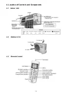
Page 12: ...12 4 Location of Controls and Components 4 1 Indoor Unit 4 2 Outdoor Unit 4 3 Remote Control ...
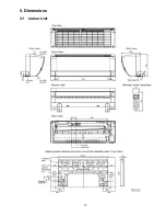
Page 13: ...13 5 Dimensions 5 1 Indoor Unit ...
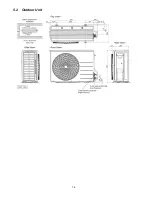
Page 14: ...14 5 2 Outdoor Unit ...
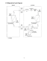
Page 15: ...15 6 Refrigeration Cycle Diagram ...
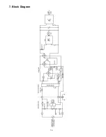
Page 16: ...16 7 Block Diagram ...
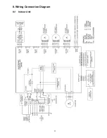
Page 17: ...17 8 Wiring Connection Diagram 8 1 Indoor Unit ...
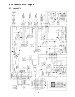
Page 19: ...19 9 Electronic Circuit Diagram 9 1 Indoor Unit ...
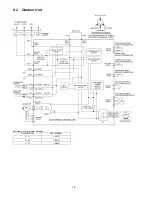
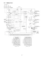
Page 20: ...20 9 2 Outdoor Unit ...
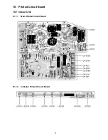
Page 23: ...23 10 2 Outdoor Unit 10 2 1 Main Printed Circuit Board ...
Page 29: ...29 ...
Page 91: ...91 Figure 3 Figure 4 16 1 1 3 To remove discharge grille Figure 5 ...
Page 93: ...93 Figure 8 Figure 9 ...
Page 94: ...94 Figure 10 ...


