58
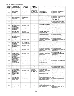
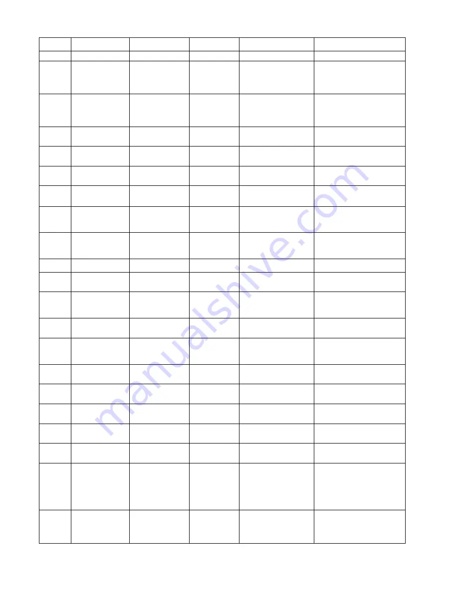
15.3 Error Code Table
Diagnosis
display
Abnormality /
Protection control
Abnormality
Judgment
Protection
Operation
Problem Check
location
H00
No memory of failure
—
Normal operation
—
—
H11
Indoor/outdoor
abnormal
communication
After operation for
1 minute
Indoor fan only
operation can
start by entering
into force cooling
operation
Indoor/outdoor
communication not
establish
•
Indoor/outdoor wire terminal
•
Indoor/outdoor PCB
•
Indoor/outdoor connection wire
H12
Indoor unit capacity
unmatched
90s after power
supply
—
Total indoor capability
more than maximum limit
or less than minimum limit,
or number of indoor unit
less than two
•
Indoor/outdoor connection wire
•
Indoor/outdoor PCB
•
Specification and combination
table in catalogue
H14
Indoor intake air
temperature sensor
abnormality
Continuous for 5s
—
Indoor intake air
temperature sensor open
or short circuit
•
Indoor intake air temperature
sensor lead wire and connector
H15
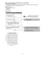
Compressor
temperature sensor
abnormality
Continuous for 5s
—
Compressor temperature
sensor open or short circuit
•
Compressor temperature
sensor lead wire and connector
H16
Outdoor current
transformer (CT)
abnormality
— —
Current transformer faulty
or compressor faulty
•
Outdoor PCB faulty or
compressor faulty
H19
Indoor fan motor
merchanism lock
Continuous
happen for 7 times
—
Indoor fan motor lock or
feedback abnormal
•
Fan motor lead wire and
connector
•
Fan motor lock or block
H23
Indoor heat
exchanger
temperature sensor
abnormality
Continuous for 5s
—
Indoor heat exchanger
temperature sensor open
or short circuit
•
Indoor heat exchanger
temperature sensor lead wire
and connector
H24
Indoor heat
exchanger
temperature sensor
2 abnormality
Continuous for 5s
—
Indoor heat exchanger
temperature sensor 2 open
or short circuit
•
Indoor heat exchanger
temperature sensor 2 lead wire
and connector
H25
Indoor ion device
abnormality
Port is ON for 10s
during ion device off
— —
•
ion device PCB
H27
Outdoor air
temperature sensor
abnormality
Continuous for 5s
—
Outdoor air temperature
sensor open or short circuit
•
Outdoor air temperature sensor
lead wire and connector
H28
Outdoor heat
exchanger
temperature sensor
1 abnormality
Continuous for 5s
—
Outdoor heat exchanger
temperature sensor 1 open
or short circuit
•
Outdoor heat exchanger
temperature sensor 1 lead wire
and connector
H30
Outdoor discharge
pipe temperature
sensor abnormality
Continuous for 5s
—
Outdoor discharge pipe
temperature sensor open
or short circuit
•
Outdoor discharge pipe
temperature sensor lead wire
and connector
H32
Outdoor heat
exchanger
temperature sensor
2 abnormality
Continuous for 5s
—
Outdoor heat exchanger
temperature sensor 2 open
or short circuit
•
Outdoor heat exchanger
temperature sensor 2 lead wire
and connector
H33
Indoor / outdoor
misconnection
abnormality
— —
Indoor and outdoor rated
voltage different
•
Indoor and outdoor units check
H34
Outdoor heat sink
temperature sensor
abnormality
Continuous for 2s
—
Outdoor heat sink
temperature sensor open
or short circuit
•
Outdoor heat sink sensor
H36
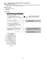
Outdoor gas pipe
temperature sensor
abnormality
Continuous for 5s
Heating
protection
operation only
Outdoor gas pipe
temperature sensor open
or short circuit
•
Outdoor gas pipe temperature
sensor lead wire and connector
H37
Outdoor liquid pipe
temperature sensor
abnormality
Continuous for 5s
Cooling
protection
operation only
Outdoor liquid pipe
temperature sensor open
or short circuit
•
Outdoor liquid pipe temperature
sensor lead wire and connector
H38
Indoor/Outdoor
mismatch (brand
code)
—
—
Brand code not match
•
Check indoor unit and outdoor
unit
H39
Abnormal indoor
operating unit or
standby units
3 times happen
within 40 minutes
—
Wrong wiring and
connecting pipe, expansion
valve abnormality, indoor
heat exchanger sensor
open circuit
•
Check indoor/outdoor
connection wire and connection
pipe
•
Indoor heat exchanger sensor
lead wire and connector
•
Expansion valve and lead wire
and connector
H41
Abnormal wiring or
piping connection
— —
Wrong wiring and
connecting pipe, expansion
valve abnormality
•
Check indoor/outdoor
connection wire and connection
pipe
•
Expansion valve and lead wire
and connector
Summary of Contents for CS-AE9NKE
Page 12: ...12 4 Location of Controls and Components 4 1 Indoor Unit 4 2 Outdoor Unit 4 3 Remote Control ...
Page 13: ...13 5 Dimensions 5 1 Indoor Unit ...
Page 14: ...14 5 2 Outdoor Unit ...
Page 15: ...15 6 Refrigeration Cycle Diagram ...
Page 16: ...16 7 Block Diagram ...
Page 17: ...17 8 Wiring Connection Diagram 8 1 Indoor Unit ...
Page 19: ...19 9 Electronic Circuit Diagram 9 1 Indoor Unit ...
Page 20: ...20 9 2 Outdoor Unit ...
Page 23: ...23 10 2 Outdoor Unit 10 2 1 Main Printed Circuit Board ...
Page 29: ...29 ...
Page 91: ...91 Figure 3 Figure 4 16 1 1 3 To remove discharge grille Figure 5 ...
Page 93: ...93 Figure 8 Figure 9 ...
Page 94: ...94 Figure 10 ...

