background image

56

CQ-C5400/5300/5100W

CQ-C5400/5300/5100W

57

Installation Guide 

(continued)

8

 Lock cancel plate

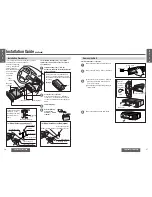
Remove the Unit

Switch off the power of the unit.

1

Remove the removable face plate (page 51).

2

Remove the trim plate 

7

 with a screwdriver.

3

1

  Insert the lock cancel plates 

8

 along the 

grooves on both sides of the main unit 
until “click” is heard.

2

  Pull out the unit while pushing the plates 

further inside.

4

Remove the unit pulling with both hands.

7

 Trim  plate

1

  Insert.

Insert the tab 
end in the 
outer groove.

Screwdriver

2

  Pull  out.

“Click”

E
N

G

L

I

S
H

33

E
N

G

L

I

S
H

34

Installation Procedures

The included mounting collar 

1

 is designed 

specifi cally for this unit. Do not use it to attach 
any other model.

6

 Power 

connector

Engage the mounting 
springs (

§

) in the 

mounting holes of the 
mounting collar 

1


fi rmly.

The tabs to be bent vary depending on 
the car. To securely install the unit, fully 
bend a number of the tabs so that there is 
no rattling.

(b) Using the rubber cushion (option)

1

Insert mounting collar 

1

 into the 

dashboard, and bend the mounting tabs out 
with a screwdriver.

2

Secure the rear of the unit.

After fi xing mounting bolt 

5

 and power 

connector 

6

, fi x the rear of the unit to the 

car body by either method 

(a)

 or 

(b)

 shown 

below.

3

Insert trim plate 

7

.

4

After installation, 
reconnect the 
negative 

-

 battery 

terminal.

Mounting holes

Mounting 
springs (

§

)

5

 Mounting  bolt

Mounting springs (

§

)

Mounting 
hole

(a) Using the rear support strap 

3

4

 Tapping  screw

Fire wall of car

2

 Hex.  nut

3 mm

·

3

 Rear support strap

5

 Mounting  bolt

1

 Mounting  collar

Rubber cushion (option)

Rear support bracket
(provided on the car)

5

 Mounting  bolt

1

 Mounting  collar

Tab

First complete the electrical connections, and then 
check them for correctness (page 58).

Example:

Remove the mounting 
collar 

1

 and the trim 

plate 

7

 from the 

main unit temporarily, 
which are already 
mounted at 
shipment.

Summary of Contents for CQ-C5400

Page 1: ...e Full Front MP3 WMA CD Player Receiver with CD Changer Control CQ C5400 C5300W Removable Full Front CD Player Receiver with CD Changer Control CQ C5100W CQ C5400W Operating Instructions Operating Instructions ...

Page 2: ...CEDURES OTHER THAN THOSE SPECIFIED HEREIN MAY RESULT IN HAZARDOUS RADIATION EXPOSURE DO NOT OPEN COVERS AND DO NOT REPAIR BY YOURSELF REFER SERVICING TO QUALIFIED PERSONNEL Precautions Page 8 Accessories 9 Features 12 Before Reading these Instructions 13 Control Reference Guide 14 Preparation 16 Clock Setting 17 General 24 Radio 28 Before Disc Playback 30 CD Player 31 MP3 WMA Player 32 CD Changer ...

Page 3: ...30 Note The preset memory is cleared to return to the original factory setting when the power connector or battery is disconnected Item Diagram Q ty Remote Control Unit YEFX9992663 1 Remote Control Unit YEFX9992013 1 Lithium Battery CR2025 1 Operating Instruction YEFM284149 1 Mounting Collar YEFX0216165 1 Trim Plate YEFC05606 1 Trim Plate YEFC05608 1 Accessories 6 4 9 7 5 Car Audio SOURCE MUTE POW...

Page 4: ...licable to Features MP3 WMA Playback from CD R RW You can play your MP3 WMA Windows Media Audio files as well as regular CDs With up to 10 to 12 times the capacity of a conventional CD a single MP3 WMA encoded disc can keep you entertained throughout your entire journey Depending on bit rate SQ7 7 bands Sound Quality SQ is a function that can call up various sound types at the touch of button in a...

Page 5: ...zer level SQ adjustment page 39 Enters the number input mode page 31 33 37 Changes the display page 17 28 31 32 36 Selects a band page 28 Sets a preset station APM Auto Preset Memory page 29 CD play pause page 31 32 Direct track file folder disc selection page 31 33 37 Adjusts the function settings page 43 6 4 9 7 5 Car Audio SOURCE MUTE POWER RAND VOL 3 1 2 DISP BAND REP 6 5 SET SEL SCAN MENU NUM...

Page 6: ...he holder out at position B while pushing position A as indicated 2Install the battery on the battery holder 3Insert the battery holder back into its original position Battery Notes Battery type Panasonic lithium battery CR2025 included Battery life Approximately 6 months under normal use at room temperature Remove and dispose of an old battery immediately Do not disassemble or short the battery D...

Page 7: ...s connected CD changer control page 36 AUX page 59 or CQ C5100W Radio page 28 CD player page 31 When an optional CD changer is connected CD changer control page 36 No sounds default Decrease the volume by 10 steps DISP Display Scrolling Level meter This varies the display in line with the volume level Point the remote control unit at the remote control signal sensor Spectrum analyzer This shows tw...

Page 8: ...T will be retained even when the operations below are performed OPEN CLOSE Power on off Flat frequency response not emphasize default Prevention of excessive equalizing and capability to cover wide variety of music Listener friendly and crisp sound Sharp and dynamic sound Powerful deep bass and turgescent treble Highlighted vocals that are apt to be overwhelmed by instrumental sound Sound with emp...

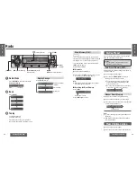
Page 9: ...tons from 1 to 6 Radio Direct Memory D M This is a useful function that can call broadcast stations directly during playback in other modes CD CD Changer etc even when the power is off Your favorite radio station can be memorized in D M direct memory Default FM 87 50 MHz Memorize 1Select a band and frequency 2Press and hold D M for more than 2 seconds Frequency is saved in the memory Note New stat...

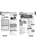
Page 10: ... once fl is pressed Note The power will be turned on automatically when a disc is loaded A disc which has both CD DA data and MP3 WMA data on it may not be reproduced normally For example it may be reproduced without sound Refer to the section on Notes on MP3 WMA page 34 and Notes on Discs page 50 E N G L I S H 7 E N G L I S H 8 CD Player Do not watch the scroll display while driving Only for CQ C5...

Page 11: ... hold 4 RANDOM for more than 2 seconds lights Press and hold 4 RANDOM again for more than 2 seconds to cancel Scan Play The first 10 seconds of each files is played in sequence Press 5 SCAN Press 5 SCAN again to cancel Folder Scan Play From the next folder the first 10 seconds of the first file on each folder is played in sequence Press and hold 5 SCAN for more than 2 seconds Press and hold 5 SCAN...

Page 12: ... Files on the previous page Compression method Bit rate VBR Sampling frequency MPEG 1 audio layer 3 MP3 32 kbps 320 kbps Yes 32 44 1 48 kHz MPEG 2 audio layer 3 MP3 8 kbps 160 kbps Yes 16 22 05 24 kHz Windows Media Audio Ver 2 Ver 8 Ver 9 64 kbps 192 kbps No 32 44 1 48 kHz Copyright It is prohibited by copyright laws to copy distribute and deliver copyrighted materials such as music without the ap...

Page 13: ...nger mode Random Play All the available tracks are played in a random sequence Press 4 RANDOM lights Press 4 RANDOM again to cancel Disc Random Play All the available tracks on the current disc are played in a random sequence Press and hold 4 RANDOM for more than 2 seconds lights Press and hold 4 RANDOM again for more than 2 seconds to cancel Scan Play The first 10 seconds of each track is played ...

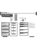
Page 14: ...fluenced one another If the influence mentioned above causes distortion to the audio signal readjust bass treble or volume To return an adjusted SQ to the default setting page 39 2Turn VOLUME Press VOL or VOL VOLUME Increased VOLUME Decreased VOLUME Increased VOLUME Decreased E N G L I S H 15 E N G L I S H 16 Push Select Select Select Select VOLUME VOLUME Adjust 1Press or to select a frequency Inc...

Page 15: ...ult BAL balance CNT center FAD fader CNT center Setting range 15 levels each Subwoofer Level You can change the subwoofer volume level Default 0 dB Setting range MUTE subwoofer mute j6 dB to i6 dB by 2 dB Subwoofer Low Pass Filter LPF You can select the upper limit frequency of the sound from subwoofer Default 80 Hz Setting range 80 Hz 120 Hz 160 Hz 2Turn VOLUME Press VOL or VOL VOLUME Right enhan...

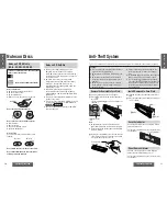
Page 16: ...n Allows you to activate the anti theft function when leaving your car Default ON Security function is activated Security function is not activated Select Select Security Function When the key in the ignition is turned OFF Security message will be displayed The panel removal alarm will be active page 51 When the front panel is removed The security indicator blinks page 51 Example Radio mode The on...

Page 17: ...e the speaker with new one The speaker channels are reversed between right and left The speaker wiring is confused between right and left Perform the speaker wiring in accordance with the wiring diagram Poor reception or noise Antenna installation or wiring of antenna cable is faulty Check whether the antenna mounting position and its wiring are correct In addition check to see whether the antenna...

Page 18: ... In case that the disc forced ejection does not work consult the dealer The microcontroller in the unit operates abnormally due to noise or other factors Unplug the power cord and plug it again In case the unit is still out of order consult the dealer Problem Possible cause Possible solution No response to pressing buttons The battery is inserted in the wrong direction A wrong battery is inserted ...

Page 19: ...ontinues if you cannot switch off the power No disc is in the changer magazine Insert discs into the changer magazine The changer has become disconnected from this unit in the changer mode Verify that correct connections have been made Maintenance Your product is designed and manufactured to ensure a minimum of maintenance Use a dry and soft cloth for routine exterior cleaning Never use benzine th...

Page 20: ...not remove the face plate while driving your car Do not place the face plate on the dashboard or nearby areas where the temperature rises to high level Do not touch the contacts on the face plate or on the main unit since this may result in poor electrical contacts If dirt or other foreign substances get on the contacts wipe them off with a clean and dry cloth To avoid damaging the face plate do n...

Page 21: ...re you begin installation look for the items which are packed with your unit Panasonic Service Station List for Service Directory Keep for future reference in case the product needs servicing Installation Hardware Needed for in dash installation Installation Hardware 12 V DC Test bulb Electrical tape Side cut pliers Dashboard Specifications Thickness Min 4 75 mm Max 5 56 mm 182 mm 53 mm Installati...

Page 22: ...k Antenna Connect the antenna by plugging the antenna lead into the antenna receptacle Installation Guide continued Identify All Leads The first step in installation is to identify all the car wires you ll use when hooking up your sound system As you identify each wire we suggest that you label it using masking tape and a permanent marker This will help avoid confusion when making connections late...

Page 23: ...t vary depending on the car To securely install the unit fully bend a number of the tabs so that there is no rattling b Using the rubber cushion option 1 Insert mounting collar 1 into the dashboard and bend the mounting tabs out with a screwdriver 2 Secure the rear of the unit After fixing mounting bolt 5 and power connector 6 fix the rear of the unit to the car body by either method a or b shown ...

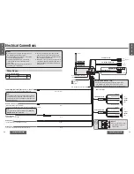
Page 24: ...ower control when an external power amplifier is connected The power supply of a power amplifier will be activated when turning on the power of this unit Antenna control lead to motor antenna max 100 mA This lead is not intended for use with switch actuated power antenna ACC power lead To ACC power i12 V DC Battery lead To the car battery continuous i12 V DC Ground lead To a clean bare metallic pa...

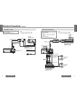
Page 25: ...on 4 channel power amplifier CY M9054EN option bridged connection RCA cord option Rear speaker option RCA cord option Stereo mono power amplifier CY M7052EN option bridged connection Front speaker option External amplifier control power lead Blue white stripe Speaker System Connection Example combination Stereo mono power amplifier CY M7052EN option 4 channel power amplifier CY M9054EN option Subw...

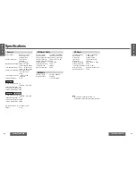
Page 26: ...r center frequency 60 Hz 160 Hz 400 Hz 1 kHz 3 kHz 6 kHz 16 kHz Variable range of equalizer 12 dB to 12 dB 2 dB step Speaker impedance 4 8 Pre amp output voltage 5 V CD mode 1 kHz 0 dB Subwoofer output voltage 5 V Pre amp output impedance 60 Subwoofer output impedance 60 Pre amp output voltage 2 5 V CD mode 1 kHz 0 dB Subwoofer output voltage 2 5 V Pre amp output impedance 200 Subwoofer output imp...

Reviews: