background image

104

3. System settings

3-3. Button assignments

3-3-1. Setting the user buttons

The user can assign several functions which can be set using 
the menu items into eight user buttons (U1 to U8).
The user buttons light in amber when the assigned function is 
ON and are off when the assigned function is OFF. 
Each time the user button is pressed, the function setting 
alternates between ON and OFF.

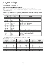
The table below lists the functions which can be assigned to 
the user buttons (U1 to U8).

Function name

Description of function

Key PVW

Output the key image to the preview output.

PinP PVW

Outputs the PinP1 and PinP2 images 
simultaneously to the preview output.

PinP1 PVW

Output the PinP1 image to the preview output.

PinP2 PVW

Output the PinP2 image to the preview output.

DSK PVW

Output the DSK image to the preview output.

GPII-EN

Enables or disables GPI-In.

GPIO-EN

Enables or disables GPI-Out.

SHIFT

Switches all the A/B bus and AUX bus 
crosspoints between front and rear.

AUX Trans

Enables or disables the AUX bus transitions.

PinP Trans

Enables or disables the PinP bus transitions.

EFF DSLV

Switches effect dissolve between ON and 
OFF.

w

   Default settings

Button

Function name

Button

Function name

U1

KEY PVW

U5

AUX Trans

U2

PinP PVW

U6

EFF DSLV

U3

DSK PVW

U7

SHIFT

U4

PinP Trans

U8

None


When a plug-in software application is introduced, the 
functions inherent to that application are sometimes 
added as the functions which are assigned.

<Setting method>

Press the 

s

 button to light its indicator, and display the 

Config menu.

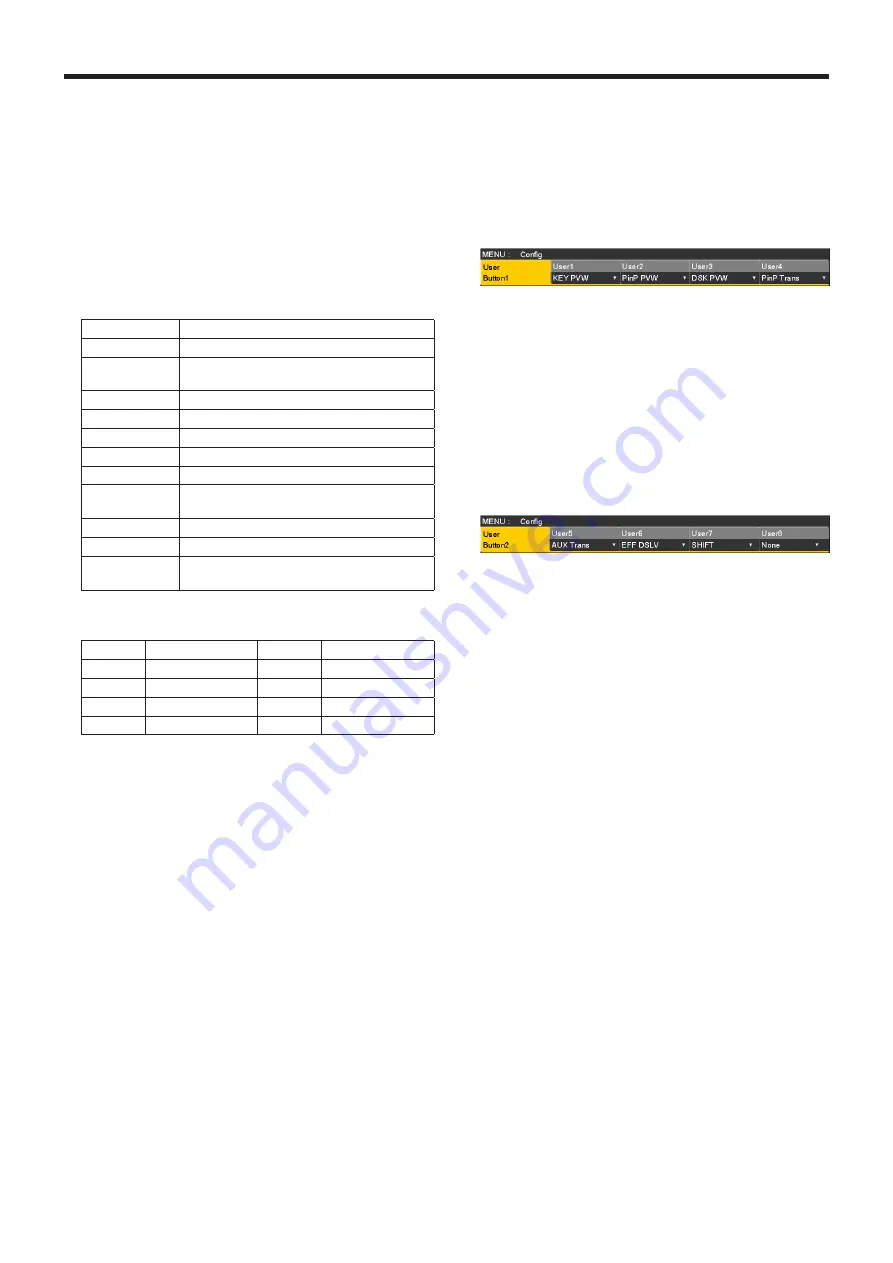
Use [F1] to display the User Button1 sub menu and 
User Button2 sub menu.


User Button1 sub menu

Use [F2] to select the function to be assigned to the 
[U1] button using the User1 item.

Use [F3] to select the function to be assigned to the 
[U2] button using the User2 item.

Use [F4] to select the function to be assigned to the 
[U3] button using the User3 item.

Use [F5] to select the function to be assigned to the 
[U4] button using the User4 item.


User Button2 sub menu

Use [F2] to select the function to be assigned to the 
[U5] button using the User5 item.

Use [F3] to select the function to be assigned to the 
[U6] button using the User6 item.

Use [F4] to select the function to be assigned to the 
[U7] button using the User7 item.

  Use [F5] to select the function to be assigned to the 

[U8] button using the User8 item.

Summary of Contents for AV-HS410E

Page 1: ...on with the required equipment and for installation Before installing this unit be sure to take the time to read through Basics to ensure that the unit will be installed correctly Operations and Settings this manual This Operations and Settings describes how to operate the unit and how to establish its settings For details on how to perform the basic menu operations refer to 2 2 Basic menu operati...

Page 2: ... Incorporated in the United States and or other countries p p SDHC Logo is a trademark of SD 3C LLC p p Primatte is a registered trademark of IMAGICA DIGIX Inc p p The copyrights of Primatte belong to IMAGICA DIGIX Inc p p The patents for Primatte belong to IMAGICA DIGIX Inc p p Other names of companies and products contained in these Operating Instructions may be trademarks or registered trademar...

Page 3: ...1 5 2 Selecting the DSK material 35 1 5 3 DSK transitions 36 1 5 4 DSK preview 36 1 5 5 DSK adjustments 36 1 5 6 DSK decorations 37 1 5 7 Masking the DSK signals 38 1 6 Key Link 39 1 7 FTB Fade to Black 40 1 8 Internal color signals 41 1 8 1 Setting the color background 41 1 8 2 Setting the Wash effect 41 1 9 Switching the AUX output 43 1 9 1 Selecting the AUX output materials 43 1 9 2 AUX1 transi...

Page 4: ...w display 96 2 5 1 Setting the screen layout 96 2 5 2 Setting the split frame and characters 97 2 5 3 Setting the tally displays 97 2 5 4 Changing the material names 98 2 5 5 Setting the level meters 99 2 5 6 Setting the input signal marks 99 2 5 7 Setting the markers 99 2 5 8 High resolution multi view mode 99 2 6 Setting the ancillary data and embedded audio data 100 3 System settings 101 3 1 Se...

Page 5: ...CONVENIENCE OR LOSS OR DAMAGE ARISING OUT OF THE SYSTEM COMBINED BY THE DEVICES OF THIRD PARTY 6 ANY INCONVENIENCE DAMAGES OR LOSSES RESULTING FROM ACCIDENTS CAUSED BY AN INADEQUATE INSTALLATION METHOD OR ANY FACTORS OTHER THAN A DEFECT IN THE PRODUCT ITSELF 7 LOSS OF REGISTERED DATA CAUSED BY ANY FAILURE 8 ANY DAMAGE OR CLAIMS DUE TO LOSS OR LEAKAGE OF IMAGE DATA OR SETTING DATA SAVED ON THIS UNI...

Page 6: ...ls 1 to 12 and rear materials 13 to 24 can be allocated to the three groups of 12 crosspoint buttons whether these buttons are the PGM A bus crosspoint buttons PST B bus crosspoint buttons or AUX bus crosspoint buttons There are actually two SHIFT functions All SHIFT for switching all the front materials to the rear materials or vice versa and Single SHIFT for switching the front material of one c...

Page 7: ...will be switched to the front materials p p When the crosspoint buttons are held down the button numbers and the names of the input materials assigned to the buttons are displayed on the built in display in the form of a list for as long as the crosspoint buttons remain held down 1 1 3 Selecting the bus mode Select the A B bus system or flip flop system PGM PST system from the setting menu 1 Press...

Page 8: ...hile the fader lever is being operated p p The auto transition time is set using the Time menu 1 Press the t button to light its indicator and display the Time menu 2 Use F1 to display the BKGD sub menu 3 Set the transition time When setting the transition time in frame units Use F4 to set the transition time in frames When setting the transition time in second units Use F3 to set the time in seco...

Page 9: ...f the number keys to select the pattern 4 Use F5 to close the table screen p p The table screen can also be closed by pressing the BKGD PATT button or KEY PATT button and turning off the button s indicator w w Table of wipe patterns p p The SQ2 8 pattern takes effect when the KEY PATT button has been pressed 4 INS MENU INPUT VMEM BKGD PATT KEY PATT TAKE ENTER PAGE PLAY REC STOP XPT DSBL CLIP 1 STI...

Page 10: ...ons Setting the border and soft effect 1 Press the b button to light its indicator and display the Background menu 2 Use F1 to display the Border sub menu 3 Use F2 to set On or Off for the border using the Border item 4 Use F3 to set the width of the border using the Width item 5 Use F4 to set the amount of soft effect using the Soft item When On has been selected as the Border item setting the ra...

Page 11: ...s from the bottom left and wipe is performed while the screen or key moves to the screen center X Pos Y Pos setting range Inside screen area Outside screen area 5 To copy the start position setting press F5 Copy to Key or Copy to BKGD The background setting is copied to the key setting while the key setting is copied to the background setting 1 2 5 Modifying wipe Setting the 3D page turning effect...

Page 12: ...an be seen around the material When HD has been selected as the system format setting 16 9 is displayed on the menu but when SD has been selected as the system format setting On is displayed on the menu 4 3 For trimming using the 4 3 aspect ratio and releasing the trimming when the transition is completed 4 3Smth For trimming using the 4 3 aspect ratio and executing the transition to 16 9 images s...

Page 13: ...ill be no original image remaining when wipe is completed when SQ1 SQ2 SL 3D1 or 3D2 has been selected as the wipe pattern Minimum The image is not delayed However the image will be delayed by one frame 1F when SQ1 SQ2 SL 3D1 or 3D2 has been selected as the wipe pattern or when the flying key has been selected BKGD items Delay amount setting At times other than during transitions MIX WIPE SQ SL 3D...

Page 14: ... using the images on the full screen as the key source signals PinP combinations are possible in conjunction with the flying key See 1 3 9 Flying key Since the luminance and chroma keys are operated as self keys the key fill signals are used as the key source signals For the full key the images on the full screen are used as the key source signals When the luminance key chroma key or full key has ...

Page 15: ...urce signal by using the Key Fill Src item Independent The key fill signal and key source signal are set separately Fill To Source When the key fill signal is selected the key source signal changes automatically Source To Fill When the key source signal is selected the key fill signal changes automatically Independent When the KEY button lights in amber the key fill signal can be selected and when...

Page 16: ...s the BKGD button and KEY button together to turn on both indicators CUT AUTO MIX MIX WIPE N R R BKGD KEY KEY ON FTB ON PinP1 ON PinP2 ON DSK ON WIPE DIRECTION WIPE MIX WIPE 2 Select the transition type Use the MIX button or WIPE button in the transition area to select the key transition mode The selected button lights in amber and the MIX or WIPE status indicator LED depending on the selected mod...

Page 17: ...for the SQ1 5 SQ2 1 2 4 to 7 3D1 5 and 3D2 1 to 3 patterns The same operations are performed for normal and reverse 5 Execute the transition Press the AUTO button in the transition area to automatically execute the transition at the transition time that has been set Alternatively execute the transition manually by operating the fader lever Key auto transition When the KEY ON button in the transiti...

Page 18: ...ing is not selected Menu User button When the user button is pressed On Lights Off Extinguished Off Extinguished On Lights Auto Extinguished On Lights When Auto is selected using a menu operation the user button indicator is turned off extinguished 1 3 5 Adjusting the luminance key and linear key These steps are taken to adjust the luminance key and linear key definition 1 Press the k button to li...

Page 19: ...y menu 2 Use F1 to display the Sample sub menu 3 Use F2 to select Composite composite image that combines the background image and key using the View item 4 Use F3 to select Select BG Color using the Mode item Select BG Color A color for the background of the foreground image is specified Normally either a blue or green background is specified 5 Use the positioner to move the position of the sampl...

Page 20: ...pling has been executed press F5 The number of operations that can be undone is one only After the noise is removed Before the noise is removed Step 3 The objective of this step is to remove the noise in the foreground image The noise is removed by carrying out this step several times 1 Use F2 to select Matte Matte image using the View item 2 Use F3 to select Clean FG Noise using the Mode item Cle...

Page 21: ...fter sampling has been executed press F5 The number of operations that can be undone is one only p p Execute sampling in both the light and dark areas as the sample area p p If the noise in the foreground image is not completely removed by carrying out the steps above proceed with the FineTuning sub menu operation Step 5 The objective of this step is to finely adjust the image by adjusting the noi...

Page 22: ...p through repeated sampling Spill Matte Matte In these modes the matte information is adjusted If for instance the area of shadow in the foreground image is to be made lighter use Matte to adjust Conversely to make it darker use Matte Transparent images such as images of smoke or water can be made to stand out more Matte ...

Page 23: ... Sponge only the semi transparent keys are made matte non transparent while the colors remain unchanged and the original colors are not restored Make FG Trans In this mode the transparency of areas with a low transparency in the foreground image is increased This is useful when for instance areas covered with dark smoke or clouds in a foreground image are to be made semi transparent Restore Detail...

Page 24: ...F3 clockwise the matte of the colors closely resembling the colors of the foreground image can be adjusted using the Trans item This is useful when for instance areas covered with dark smoke or clouds in a foreground image are to be made semi transparent 9 By turning F4 clockwise the matte information for the colors closely resembling the colors of the background image can be adjusted using the De...

Page 25: ...Edge Fill settings Materials to be inserted as edges can be set 1 On the Key menu use F1 to display the Edge2 sub menu 2 Use F2 to select the edge material using the Edge Fill items Color The color set using Edge Color is used CBGD1 The color background is used CBGD2 Still1 The still image video memory Still1 is used Still2 The still image video memory Still2 is used Clip1 The moving image video m...

Page 26: ...m On The mask signal is inverted Off The mask signal is not inverted 5 Use F1 to display the Mask Adjust sub menu 6 Use F2 to F5 to set the area to be masked Operation Parameter Description of setting Setting range Initial value F2 Left Key left position 50 00 to 50 00 25 00 F3 Top Key top position 50 00 to 50 00 25 00 F4 Bottom Key bottom position 50 00 to 50 00 25 00 F5 Right Key right position ...

Page 27: ...hanged when the size is changed PinP combinations using the flying key When Full is selected using the Type item in 1 3 1 Selecting the key type PinP combinations can be performed using the flying key At this point in time the Clip item and Gain item cannot be set on the Adjust sub menu With the full key the image on the full screen serves as the key source signal so an edge will not be added unle...

Page 28: ...al has been selected the effect to be produced when images are switched can be executed as a MIX transition Bus transition function p p When one material set to the Dot by Dot mode and another material have been switched cut switching where the images change in an instant is performed 1 Press the t button to light its indicator and display the Time menu 2 Use F1 to display the PinP1 BUS Trans sub ...

Page 29: ... or off every time the user button is pressed When PinP PVW is assigned to a user button the PinP1 image and PinP2 image preview outputs are simultaneously turned on or off every time the user button is pressed Refer to 3 3 1 Setting the user buttons 1 4 5 PinP transitions 1 Set the transition time On the Time menu use F1 to display the PinP1 sub menu or PinP2 sub menu As with background transitio...

Page 30: ...t the dot by dot mode When the system is set to the HD mode and an SD format image is to be used for the PinP material the images can be combined in the dot by dot mode actual size images In this mode the SD format image will not be up converted so image deterioration can be prevented p p When 100 00 has been selected as the Size item setting on the Position sub menu the size used for the combinat...

Page 31: ...he Symmetry item The image serving as the reference is the PinP image of the menu being operated When X has been selected as the Symmetry setting The coordinates and rotation angle are made symmetrical to the X axis When Y has been selected as the Symmetry setting The coordinates and rotation angle are made symmetrical to the Y axis When Center has been selected as the Symmetry setting The coordin...

Page 32: ...icated as the amount of soft effect When only the soft effect is to be added to PinP select Off as the Border item setting 6 Use F5 to set the change in the border width using the Mode item Fix The border width is kept constant Variable The border width changes to suit the PinP size Setting the border color 1 On the PinP1 menu or PinP2 menu use F1 to display the Border Color sub menu 2 Use F2 F3 a...

Page 33: ...milarly the Top setting cannot exceed the Bottom setting and vice versa Pair The settings are changed in such a way that the Left and Right trimming amounts and the Top and Bottom trimming amounts are the same This makes for a top bottom and left right symmetry 5 Use F1 to display the Trim Adjust sub menu and use F2 F3 F4 and F5 to set the trimming values Operation Parameter Description of setting...

Page 34: ...und and black characters etc can be reversed using the key invert function for use 4 When the luminance key has been selected the chroma components can be contained in the key signals generated in view of the fact that it is used as a self key This is not applied to the linear key Use F3 to select the setting using the Lum Key item Chroma On In addition to the luminance components the chroma compo...

Page 35: ...signal by using the DSK Fill Src item Independent The DSK fill signal and DSK source signal are set separately Fill To Source When the DSK fill signal is selected the DSK source signal changes automatically Source To Fill When the DSK source signal is selected the DSK fill signal changes automatically Independent When the DSK button lights in amber the DSK fill signal can be selected and when it l...

Page 36: ...ed 1 5 4 DSK preview Select whether to output the DSK preview image to the preview output 1 Press the d button to light its indicator and display the DSK menu 2 Use F1 to display the DSK sub menu 3 Use F5 to set the PVW item On An image with the DSK effect added is output to the preview output Off An image without the DSK effect added is output to the preview output The PVW On and Off settings can...

Page 37: ...g Edge Fill Materials to be inserted as edges can be set 1 On the DSK menu use F1 to display the Edge2 sub menu 2 Use F2 to select the edge material using the Edge Fill item Color The color set using Edge Color is used CBGD1 The color background is used CBGD2 Still1 The still image video memory Still1 is used Still2 The still image video memory Still2 is used Clip1 The moving image video memory Cl...

Page 38: ...m On The mask signal is inverted Off The mask signal is not inverted 5 Use F1 to display the Mask Adjust sub menu 6 Use F2 to F5 to set the area to be masked Operation Parameter Description of setting Setting range Initial value F2 Left DSK left position 50 00 to 50 00 25 00 F3 Top DSK top position 50 00 to 50 00 25 00 F4 Bottom DSK bottom position 50 00 to 50 00 25 00 F5 Right DSK right position ...

Page 39: ...utton is On the PinP1 ON button remains On even when the KEY ON button is set to On When the PinP1 ON button is Off the PinP1 ON button remains Off even when the KEY ON button is set to Off There is no link with the auto transition operation initiated by setting the AUTO button to On when the KEY button has been selected PinP2 This links the On or Off setting of the PinP2 ON button with the On or ...

Page 40: ...yed fade in to the program image is initiated During fade in the indicator of the FTB ON button lights in red and it goes off when the transition fade in is completed If the FTB ON button is pressed at any point during a transition the direction of the transition is reversed In the FTB status the crosspoint button which is normally lit in red lights in amber Selecting the image The image to be use...

Page 41: ...what has been set so far is canceled and replaced with the preset color values p p To save the values that were set before calling the preset color refer to 1 10 Memory 1 8 2 Setting the Wash effect The gradation effect for color backgrounds can be set Selecting the Wash effect and setting the colors 1 Press the b button to light its indicator and display the Color Background menu 2 Use F1 to disp...

Page 42: ...t the gradation cycle using the Cycle item 4 Use F4 to select the gradation phase using the Phase item 5 Use F5 to select the gradation angle using the Angle item Setting the Wash movements 1 On the Color Background menu use F1 to display the CBGD1 Move sub menu or CBGD2 Move sub menu 2 Use F2 to set the gradation movement using the Move item Off No movement is set Roll The gradations are scrolled...

Page 43: ...ideo signals p p When the AUX bus for which MV has been selected is displayed on the sub screen of the multi view display the images are looped as if two mirrors were facing each other 1 9 2 AUX1 transitions The MIX transition is executed when the output signal set for AUX1 is switched 1 Press the AUX1 button of the AUX bus selector buttons The selected button and its corresponding AUX bus crosspo...

Page 44: ...be set in second units use F3 to set the seconds and F4 to set the frames Any time from 0 to 999f can be set The time which can be set when seconds are used as the display unit differs depending on the system format 59 94i max 33s09f 59 94p max 16s39f 50i max 39s24f 50p max 19s49f 24PsF max 41s15f 23 98PsF max 41s15f 5 Use F5 to set enable or disable for the transition using the Transition item En...

Page 45: ...emories can be registered The related operations are performed using the number keys Page 1 to page 10 can be specified for the page numbers of the memories Numbers 1 to 10 can be specified as the respective memory numbers for the specified page numbers Selecting the memory numbers 1 Press the SHOT MEM or EVENT MEM button of the memory to be selected 2 Press the P button The P button indicator lig...

Page 46: ...button lights 3 Select the bus BKGD KEY PinP1 or PinP2 to be registered in the memory From the Shot Memory menu or Event Memory menu select the Store Select sub menu and then select On Refer to 1 10 1 Memory registration and recall items and 1 10 6 Selecting the buses whose settings are to be registered and or played back 4 When registering the BKGD PGM A or PST B bus KEY bus PinP1 bus or PinP2 bu...

Page 47: ... registration and recall items 4 Press the RECALL button The RECALL button indicator lights up and the number key in which the memory is registered lights in green The operations of other memory buttons EVENT MEM or SHOT MEM PLUGIN MEM1 and PLUGIN MEM2 no longer take effect 5 Press the P button and press the number key 1 to 10 corresponding to the page number 6 Press the number key 1 to 10 corresp...

Page 48: ... Selecting the buses whose settings are to be registered and or played back 3 When selecting materials using the crosspoint buttons on the operation panel instead of using the registered Material selection item materials press the XPT DSBL button to light its indicator in red Refer to 1 10 1 Memory registration and recall items 4 Press the RECALL button The RECALL button indicator lights up and th...

Page 49: ...the operations stored in the memory Delete 4 INS MENU INPUT VMEM BKGD PATT KEY PATT TAKE ENTER PAGE PLAY REC STOP XPT DSBL CLIP 1 STILL 1 MEMORY WIPE PATTERN 10 KEY TRIM OFF CLIP 2 STILL 2 REV TRIM OUT TRIM IN 9 PASTE 6 MOD 3 REV C UNDO 8 COPY 5 DEL 2 7 NEW 1 0 10 STORE RE CALL EDIT DEL SHOT MEM EVENT MEM PLUGIN MEM1 PLUGIN MEM2 1 Press the SHOT MEM or EVENT MEM button of the memory whose operatio...

Page 50: ...tings When the memory is played back the settings of the registered bus are played back 1 Press the e button to light its indicator and display the Shot Memory menu or Event Memory menu 2 Use F1 to display the Recall Select sub menu 3 Use F2 to set the BKGD item F3 to set the KEY item F4 to set the PinP1 item and F5 to set the PinP2 item On The bus settings are played back when the memory is playe...

Page 51: ...3 to set the PinP bus transition using the PinP Bus item Dissolve The PinP bus images are switched using the dissolve effect Cut The PinP bus images are switched using the cut effect 5 Use F4 to select the effect used for switching the colors using the Hue Path item The following colors are targeted by Hue p p Colors of the color background p p Colors of the borders p p Colors of the edges p p Col...

Page 52: ... ENTER PAGE PLAY REC STOP XPT DSBL CLIP 1 STILL 1 MEMORY WIPE PATTERN 10 KEY TRIM OFF CLIP 2 STILL 2 REV TRIM OUT TRIM IN 9 PASTE 6 MOD 3 REV C UNDO 8 COPY 5 DEL 2 7 NEW 1 0 10 STORE RE CALL EDIT DEL SHOT MEM EVENT MEM PLUGIN MEM1 PLUGIN MEM2 EVENT MEM button 2 Press the RECALL button to light its indicator and use the P button and number keys 1 to 10 to select the event memory to be modified Refe...

Page 53: ... event and if the TAKE ENTER button is now pressed the images are played back in the same direction During reverse playback playback stops at the first event and if the TAKE ENTER button is now pressed the images are played back in the same direction Loop During normal playback playback returns instantly from the last event to the first event and what has been played back is repeated During revers...

Page 54: ...t time at the end from the Video Memory2 sub menu press F3 LAST Number key operations 4 INS MENU INPUT VMEM BKGD PATT KEY PATT TAKE ENTER PAGE PLAY REC STOP XPT DSBL CLIP 1 STILL 1 MEMORY WIPE PATTERN 10 KEY TRIM OFF CLIP 2 STILL 2 REV TRIM OUT TRIM IN 9 PASTE 6 MOD 3 REV C UNDO 8 COPY 5 DEL 2 7 NEW 1 0 10 7 Creates a new timeline 8 Copies events An event is not copied if an edit point is not over...

Page 55: ... modified 2 Operate the panel and modify the event 3 Press 6 to set the modified details the button will blink To cancel the event modification press the C button Copying events Copy Already registered events can be copied 1 Use 0 1 2 and to select the event point of the event to be copied 2 Press 8 to copy the event the button will blink Pasting events Paste Copied events can be pasted 1 Use 0 1 ...

Page 56: ...mark registration or event insertion press the C button Setting the event duration The lengths of the events can be set 1 Use 0 1 2 and to select the event to be modified 2 Press the e button to display the Event Memory menu 3 Use F1 to display the Event Duration sub menu 4 Use F2 minute item minutes F3 second item seconds and F4 frame item frames to set the event length 5 Press F5 to enter the du...

Page 57: ...ng transitions are available p p Width of the borders p p Soft effect of the borders p p Colors of the borders p p Positions of the images p p Trimming values Linear The switching from one image to another is interpolated linearly Spline The switching from one image to another is interpolated over a smooth curve a cubic function curve Step The parameters are updated when the events are passed thro...

Page 58: ...ter sub menu use F2 to select the page number of the registered memories using the Page item 2 Use F3 to select the memory number using the No item 3 Use F4 to display the keyboard screen 4 Use F1 to F3 to input the name and press F4 To cancel the name which has been input and close the keyboard screen press F5 Refer to 2 2 2 Keyboard screen operations Basics Operating Instructions Copying memorie...

Page 59: ...he images number of seconds which can be stored depends on the system format frame rate p p The video memory data can be stored onto and read out from memory cards Video memory operation Current status Clip1 Clip2 Recording Playback Stop Recording Playback Stop Still1 Recording Still2 Recording Clip1 Recording Playback Stop Clip2 Recording Playback Stop Valid Invalid Video memory input output The ...

Page 60: ...button AUX BUS DELEGATION of AUX1 to AUX4 selected in the V Source item which will light or turn off the buttons p p If the material of the DISP bus is changed the materials of the DISP bus and the selected AUX bus change at the same time Similarly if the material of the selected AUX bus is changed the material of the DISP bus changes at the same time 8 Use F3 to set the image to be recorded in th...

Page 61: ...of the selected AUX bus is changed the material of the DISP bus changes at the same time 8 Use F3 to set the image to be recorded in the video memory using the V Source item AUX1 to AUX4 The output signals of the AUX buses AUX1 to AUX4 are recorded as the material 9 Use F5 to set the review display using the Review item On After the images have been recorded the images of the video memory recorded...

Page 62: ... the data is transferred from the AUX bus or to manually save them must be set p p If power to the unit is turned off when the saving of data has not finished video memory data will be lost p p Video memory data that has been saved is always restored when the power is turned on To cancel the restoration of video memory press the VMEM button and switch to video memory operation mode and then press ...

Page 63: ...ck moving images in tandem with the transition operation Use F2 Clip1 item to set the Clip1 playback start button and use F3 Clip2 item to set the Clip2 playback start button Off Playback is not performed in tandem with the transition operation AUTO The playback of the moving images is started in tandem with the operation of the AUTO button KEY ON The playback of the moving images is started in ta...

Page 64: ...re saved to a memory card only the trimmed portion is saved p p The same position cannot be specified for the IN point and the OUT point The smallest unit available when trimming is performed is 2 frames Operations performed using the number keys 4 INS MENU INPUT VMEM BKGD PATT KEY PATT TAKE ENTER PAGE PLAY REC STOP XPT DSBL CLIP 1 STILL 1 MEMORY WIPE PATTERN 10 KEY TRIM OFF CLIP 2 STILL 2 REV TRI...

Page 65: ...ill2 Clip1 Clip2 can be shown on the built in display Thumbnail layout Still still images Still image Key signal indicator A key signal is always present for Still No key signal Key signal present Clip moving images Image in the first frame of the clip Key signal indicator No key signal Key signal present Duration of the recorded clip Duration of the range specified with trimming Current playback ...

Page 66: ...TSC format use images shrunk to 720 487 pixels If the images are in PAL format use images enlarged to 720 576 pixels Video memories moving image data Clip1 Clip2 This is the original format of the unit Data is stored in and read from these memories Shot memory data Shot Data is stored in and read from these memories Event memory data Event Data is stored in and read from these memories Setup data ...

Page 67: ...y select tga or png as the file format The still image data of any other file format cannot be stored with attaching the key signals 2 In the case of All file folders with the names specified using the File Name item are created at the hierarchical level under the ALL folder and the data is stored inside the folders which have been created The data is stored under the following filenames Still1 St...

Page 68: ...and then press the F2 5 Use F3 to select the data which is to be stored on the memory card using the Save Type item The filename provided automatically is displayed in the File Name item Filenames are provided automatically using the running number as shown below Saving the video memories shot memory data Event memory data and setup data hs001 xxx to hs100 xxx p p When changing a filename press F4...

Page 69: ... select the name of the file to be loaded using the SELECT FILE item If the name of the file to be loaded consists of more than 8 characters a shortened version of the filename will be displayed p p When Plug in has been selected using F1 SELECT item use F3 to select the index number 1 to 10 of the files to be loaded p p Up to 100 files can be loaded from one folder p p The following alphanumerics...

Page 70: ...ot 2 On the SD Card menu use F1 to display the File1 sub menu 3 Use F2 to select Delete using the Mode item and then press the F2 When F2 is pressed the file selection screen is displayed Example of what appears on the file selection screen 4 Use F1 to select the type of file to be deleted using the SELECT item If the name of the file to be loaded consists of more than 8 characters a shortened ver...

Page 71: ... onto each other and displayed 5 Use F3 to select the signals whose waveforms are to be displayed using the Mode item YPbPr Waveforms of the Y PB and PR signals are displayed RGB Waveforms of the R G and B signals are displayed Y Waveforms of the Y signal only are displayed VECTOR vectorscope settings 1 Press the WFM VECT button among the display mode buttons to display the vectorscope on the buil...

Page 72: ... The status of the embedded audio is displayed When PGM PVW MV or AUX signals are selected When ON has been selected as the ancillary data setting the status of the embedded audio is displayed STATUS Format 1080 23PsF GROUP 1 2 3 4 RATE 44 1KHz ACT 1 2 3 4 5 6 7 8 Audio group Audio rate Audio channels System formats used by the unit Display System format 1080 59i 1080 59 94i 720 59p 720 59 94p 108...

Page 73: ...Full HD DVI Input Board Before setting the input signals first select the input signal to be set using the Input sub menu 1 Press the i button to light its indicator and display the Input menu 2 Use F1 to display the Input sub menu 3 Use F2 to select the input signals using the Select item The menu display is switched in accordance with the input signals which have been selected The menu title is ...

Page 74: ... input 2 lines AV HS04M3 DVI I input 2 lines AV HS04M6 Analog composite input 2 lines AV HS04M8 DVI D input 2 lines Input connector Setting menu and numbers of sections in this manual Video Process SDI Gain Video Process Composite DVI Input Digital DVI Input Analog 2 1 7 2 1 8 2 1 9 2 1 10 2 1 10 SDI IN1 to SDI IN4 Standard SDI input 8 lines SDI IN5 SDI IN6 SDI IN7 SDI IN8 DVI IN Standard DVI D in...

Page 75: ...Refer to 2 1 Input signal settings 2 Use F1 to display the FS sub menu 3 Use F2 to set On or Off for the frame synchronizer using the FS item If the output signal phase is set to 0H Off cannot be selected as the FS item setting Line synchronizer function is active while the frame synchronizer function is set to Off The line synchronizer function automatically adjusts the input image signal phase t...

Page 76: ...en input they are up converted Auto Input signals in conformity with the system format take effect Furthermore if SD signals with the same frame rate as the system format are input when HD is selected as the system format they are up converted In the Auto mode the images may be disturbed when the input signals are switched List of input modes supported System Mode Input 480 59 94i 576 50i 1080 59 ...

Page 77: ...cancel the freeze If the F3 is pressed while the display is Off the video signal is frozen and the display is set to On If the F3 is pressed while the display is On the video signal freezing is canceled and the display is set to Off The F mark appears in front of the name of the material when the signals set for output of multi view displays are frozen p p When the unit is used with the frame sync...

Page 78: ... Use F3 to set the image movement detection sensitivity using the Move Detect item 1 Toward still images 3 Standard 5 Toward moving images 5 Use F4 to set the extent of the edge sharpness for the images using the Sharp item 1 Not sharp edges 3 Standard 5 Very sharp edges 6 Use F5 to adjust the input image size 100 to 110 Fine tuning of image positions Fine tuning of image positions is performed wh...

Page 79: ...e change in the hue using the Hue item Copying the settings The video process settings already selected can be set for other input signals as well On the Video Process2 sub menu use F5 to select the input signals of the copy destination and press F5 2 1 8 Setting the analog input gain option When the analog input board option has been connected the gain of the input signals can be set Alternativel...

Page 80: ...nal Y signal gain using the Gain item 4 Use F3 to adjust the chroma level using the Chroma item Maximum amount of variation approx 3 dB The auto color control function is activated and the chroma level is kept at the value that has been set 5 Use F4 to adjust the pedestal level using the Ped item Maximum amount of variation approx 100 mV 6 Use F5 to adjust the hue using the Hue item Maximum amount...

Page 81: ...n 1 On the Input sub menu use F2 to select the input to be set using the Select item Refer to 2 1 Input signal settings 2 Use F1 to display the DVI Input sub menu 3 Use F2 to select the signal system using the Mode item Set this when the DVI input board AV HS04M3 has been connected Digital Digital input signals of the DVI connector are effective Analog Analog input signals of the DVI connector are...

Page 82: ...0 576 XGA 1024 768 Fit V 1440 1080 720 960 487 720 576 720 Fit H 487 720 576 720 Full 1920 1080 720 1280 487 720 576 720 SXGA 1280 1024 Fit V 1350 1080 720 900 487 675 576 675 Fit H Full 1920 1080 720 1280 487 720 576 720 WXGA 1280 768 Fit V Fit H Full Black images are inserted here The parts of the images protruding in these areas are cropped ...

Page 83: ...720 1152 Fit H Full 1920 1080 720 1280 487 720 576 720 UXGA 1600 1200 Fit V 1440 1080 720 960 487 720 576 720 Fit H 487 720 576 720 Full 1920 1080 720 1280 487 720 576 720 WUXGA 1920 1200 Fit V 1728 1080 720 1152 Fit H Full 1920 1080 720 1280 487 720 576 720 Black images are inserted here The parts of the images protruding in these areas are cropped ...

Page 84: ...080 59 94p 1080 50p 1080 59 94i 1080 50i 1920 1080 Fit V 1920 1080 720 1280 Fit H 1920 1080 720 1280 Full 1920 1080 720 1280 720 59 94p 720 50p 1280 720 Fit V 1920 1080 720 1280 Fit H 1920 1080 720 1280 Full 1920 1080 720 1280 Black images are inserted here The parts of the images protruding in these areas are cropped ...

Page 85: ... DVI D formats supported Input video signal Dot clock frequency MHz Frequency Horizontal kHz Vertical Hz XGA 1024 768 Digital 65 0 48 36 60 00 WXGA 1280 768 Digital 79 5 47 78 59 87 SXGA 1280 1024 Digital 108 0 63 98 60 02 WSXGA 1680 1050 Digital 146 2 65 29 59 95 UXGA 1600 1200 Digital 162 0 75 00 60 00 WUXGA 1920 1200 Digital 154 0 74 04 59 95 1080 50p 1920 1080 Digital RGB 148 5 56 25 50 00 108...

Page 86: ...pplied CD ROM or the full screen black signals and full screen white signals on the computer connected to the DVI input connector and input these signals as the DVI input signals When using the black and white signals position them so that the boundary between black and white comes to the center of the monitor screen When using the full screen black signals or full screen white signals display the...

Page 87: ... item The menu display is switched depending on the selected output signals The menu title is set to MENU Output signal type output connector Signal type SDI Analog DVI D DVI I Example of menu SDI List of settings by output signal Output connector Setting menu and numbers of sections in this manual Assign SDI Output DVI Output Digital DVI Output Analog Down Converter 2 2 1 2 2 2 2 2 3 2 2 3 2 2 4 ...

Page 88: ...put mode using the Mode item Normal The same signals as the system format signals are output Down Convert down converter This can be selected when the SDI output board option AV HS04M7 has been connected When the system format is 1080 59 94i or 720 59 94p the signals are output in the 480 59 94i format When the system format is 1080 50i or 720 50p the signals are output in the 576 50i format When ...

Page 89: ...se F3 to select the resolution of the images to be output using the Size item Auto The equipment information of the output destination is captured by the DVI signals and the images are output at the optimum resolution The vertical frequency is 60 Hz and the maximum resolution is SXGA for analog output signals and WUXGA for digital output signals If the equipment information cannot be captured or i...

Page 90: ...parts of the images are cropped Full The size of the output images is increased or reduced in accordance with the system resolution Fullx80 The size of the output image is increased or reduced in accordance with the 80 size of the system resolution Fullx90 The size of the output image is increased or reduced in accordance with the 90 size of the system resolution p p The aspect ratio is not mainta...

Page 91: ...stem image HD Output image SD Squeeze Edge Crop Letter Box 4 Use F3 to set the delay time of the output using the Delay item 90H 75H When the system format is 1080 59 94i the image is delayed from the system image HD by 90H and output When the system format is 720 59 94p the image is delayed from the system image HD by 90H 1F frame and output When the system format is 1080 50i the image is delayed...

Page 92: ... the Reference sub menu 3 Use F2 select the sync signal using the Sync item and press the F2 to enter the selection 4 Use F3 to select the setup level of the black burst signal in the internal synchronization mode using the BB Setup item This setting takes effect when the video system is 59 94i or 59 94p The setup level is fixed at 0 IRE when the system is 50i or 50p 5 The genlock status is displa...

Page 93: ...iable Range H Phase 0 5H to 0 5H V Phase 100 lines Approx 0 3H to 1 3H Internal Fixed DL Line Synchronizer Range Reference System standard 1H Output 1H Shortest Output 0 5H Output Phase Variable Range H Phase 0 5H to 0 5H V Phase 100 lines Approx 0 3H 0 5H Internal Fixed DL Approx 0 7H to 0 3H Line Synchronizer Range H Phase 0 5H to 0 5H V Phase 100 lines Output Phase Variable Range Internal Fixed...

Page 94: ...nvert Dot by Dot On Forced Possible In phase with Reference Max 1F 1 90H Max 1F 90H In phase with 1 Max 2F Sync signal Reference Black burst signal BB Advanced 1H Normal Off Not possible Reference 90H 1H 1H 1 90H 1H 90H In phase with 1 1F 1H Normal On Possible Reference 90H 1H Max 1F 90H 1H 1 90H Max 1F 1H In phase with 1 Max 2F 90H 1H Up Convert Dot by Dot On Forced Possible 0H Example 2 Normal U...

Page 95: ... F2 F1 F2 F1 F2 Input signals non synchronized 1F frame Sync signal Reference Output signal 1 Output signal 2 90H Output signal 2 1F Max 1F Max 2F Max 1F 90H Example 2 F1 F2 F1 F2 F1 F2 F1 F2 Input signals non synchronized 1F frame Sync signal Reference Output signal 1 Output signal 2 90H Output signal 2 1F Max 1F 90H Max 2F 90H Max 1F ...

Page 96: ...Split sub menu 3 Use F2 to set the split screen display mode using the Split item 4 Use F1 to display the MV Pattern 1 4 to MV Pattern 4 4 sub menus 5 Use F2 to F5 to set the names of the signals to be displayed on the sub screens 1 to 16 SDI IN1 to SDI IN8 DVI IN IN A1 IN A2 IN B1 IN B2 CBGD1 CBGD2 Still1V Still1K Still2V Still2K Clip1V Clip1K Clip2V Clip2K PGM PVW MEM PVW Key Out AUX1 to AUX4 Cl...

Page 97: ... displayed using the Label item On The character background is displayed Off The character background is not displayed 2 5 3 Setting the tally displays Set the tally displays to be superimposed onto the split frame of the multi view display The red tally indicates material consisting of program outputs The green tally indicates material selected by the preset bus On the MV Frame sub menu use F5 to...

Page 98: ...ype item Default default settings The following material names are selected automatically SDI IN1 to SDI IN8 DVI IN IN A1 IN A2 IN B1 and IN B2 User user settings The material names are set using up to 7 characters Preset type setting procedure 1 On the Name sub menu use F2 to select Preset using the Type item 2 Use F3 to select the material name using the Name item User type setting procedure 1 O...

Page 99: ...n be displayed for the multi view materials The markers can be displayed when PGM or PVW materials are to be displayed in half their original size 4Split Sub screens 1 to 4 5 6 10Split 1 or 2 sub screens 1 On the Display sub menu use F4 to set the marker display using the Marker item 4 3 The markers are displayed using the 4 3 aspect ratio 16 9 The markers are displayed using the 16 9 aspect ratio...

Page 100: ...t materials selected by the PGM bus are allowed to pass through Off The ancillary data and embedded audio data are not allowed to pass through Setting for the preview output signals 4 Use F4 to select On or Off using the PVW item On The ancillary data and embedded audio data of the SDI input materials selected by the PST bus are allowed to pass through Off The ancillary data and embedded audio dat...

Page 101: ... to display the Format sub menu 3 Use F2 select the format using the Format item and press the F2 to enter the selection Setting the 16 9 squeeze mode When the 16 9 squeeze mode is selected a border width wipe or PinP is established that considers cases where SD format images are to be converted into the 16 9 aspect ratio and used This setting is possible when SD is selected as the system format s...

Page 102: ...k BLK Internally generated signal black CBGD1 CBGD2 CBD1 CBD2 Internally generated signal color background CBAR CBAR Internally generated signal color bar Still1V Still1K Still2V Still2K ST1V ST1K ST2V ST2K Still image video memory Clip1V Clip1K Clip2V Clip2K CL1V CL1K CL2V CL2K Moving image video memory MEM PVW MPV Memory preview AUX bus and built in display images only AUX1 to AUX4 AUX1 to AUX4 ...

Page 103: ...button to light its indicator and display the XPT menu 2 Use F1 to display the XPT Switch sub menu 3 Use F2 and select the switching timing using the Timing item Any The crosspoints are switched in the nearest field This is suited to live applications Field1 The crosspoints are switched in field 1 This is suited to editing applications Field2 The crosspoints are switched in field 2 This is suited ...

Page 104: ...ansitions EFF DSLV Switches effect dissolve between ON and OFF Default settings Button Function name Button Function name U1 KEY PVW U5 AUX Trans U2 PinP PVW U6 EFF DSLV U3 DSK PVW U7 SHIFT U4 PinP Trans U8 None p p When a plug in software application is introduced the functions inherent to that application are sometimes added as the functions which are assigned Setting method 1 Press the s button...

Page 105: ...ings to perform such tasks as updating the software version via LAN The network initial setup is IP address 192 168 0 8 subnet mask 255 255 255 0 When using the host computer with settings matching the initial setup it is not necessary to setup via the menu For the setting to take effect the system must be rebooted Turn the system s power off and then back on Entering the IP address 1 Press the s ...

Page 106: ...l 60 minutes 120 minutes 180 minutes the built in display backlight is turned off automatically Even when the set time interval elapses and the display backlight is turned off the backlight comes back on when a control panel operation is performed 4 Use F3 to set the brightness of the backlight using the Adjust item Setting the button illumination The button indicators in the areas listed below ca...

Page 107: ...he alert status of the cooling fan is displayed in the Fan item The alert status of the internal temperature is displayed in the Temperature item No Alarm No irregularity Alarm Irregularity 3 7 2 Alarm message A message is displayed on the built in display when an alarm has occurred Alarm message displayed Type of trouble Operation ALARM Fan Stop Shutdown of the cooling fan When OK is pressed the ...

Page 108: ...se F3 to select the type Soft or FPGA of the version to be displayed using the Module Type item p p The item of the module that corresponds to the selected type can be selected as the Select item using F4 When F4 is used the version of the selected item is displayed in the Version item of F5 Displaying the option version information 4 Use F1 to display the Option Version sub menu 5 Use F2 to selec...

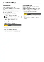
Page 109: ...me 1 Press the s button to light its indicator and display the System menu 2 Use F1 to display the Initial sub menu 3 Use F2 to select the initialization mode Mode A or Mode B 4 Press F2 to proceed with the initializing p p Once initialization has been completed the power of the unit shuts off and turns back on again automatically 3 8 2 Initializing fader The range for executing a transition can b...

Page 110: ...e ports using the GPI In Enable item or GPI Out Enable item 4 Use F3 to set the AUX bus to be used to notify the tally using the AUX Sel item 5 Use F1 to display GPI In Port 1 2 sub menu and GPI In Port 2 2 sub menu or GPI Out Port 1 5 sub menu to GPI Out Port 5 5 sub menu 6 Use F2 to F5 to allocate the functions to be assigned to the respective pin numbers Refer to Control using the GPI Input por...

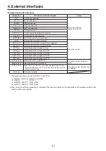
Page 111: ...hen the key is selected REC Still1 Still1 recording REC Still2 Still2 recording REC Clip1 Clip1 recording start REC Clip2 Clip2 recording start STOP Clip1 Clip1 recording stop or playback stop STOP Clip2 Clip2 recording stop or playback stop PLAY Clip1 Clip1 playback start PLAY Clip2 Clip2 playback start AUX XPT 1 to 24 Crosspoint buttons 1 to 24 used to switch the AUX buses Select the AUX buses A...

Page 112: ...K Trans Transition execution in progress for DSK PinP1 Trans Transition execution in progress for PinP1 PinP2 Trans Transition execution in progress for PinP2 FTB Trans Transition execution in progress for FTB REDTly1 to 13 Red tally for INPUT1 to INPUT13 A low level is output during tally output GRNTly1 to 13 Green tally for INPUT1 to INPUT13 AUXTly1 to 13 When INPUT1 to INPUT13 have been selecte...

Page 113: ... contact inputs AV HS410 TALLY GPI 1 1 2 3 4 5 12 11 10 6 7 8 15 14 13 9 TALLY GPI 2 1 2 3 4 5 12 11 10 6 7 8 15 14 13 9 Pin No Signal name Pin No Signal name 1 GPI Out1 1 GPI Out10 9 GPI Out9 9 GPI Out18 2 GPI Out2 2 GPI Out11 10 ALARM Out 10 GPI Out19 3 GPI Out3 3 GPI Out12 11 GPI In1 11 GPI In5 4 GPI Out4 4 GPI Out13 12 GPI In2 12 GPI In6 5 GPI Out5 5 GPI Out14 13 GPI In3 13 GPI In7 6 GPI Out6 ...

Page 114: ...eceive data 4 GROUND Ground 5 NC Not used 6 GROUND Ground 7 TXD Send data 8 RXD Receive data 9 FRAME GROUND Frame ground 4 4 COM An external device can be controlled from the unit p p It supports plug in software The communication system can be selected using the setting menu 1 Press the s button to light its indicator and display the Config menu 2 Use F1 to display the COM Port sub menu 3 Use F2 ...

Page 115: ...ame sub menu use F3 to establish the setting at startup using the Enable item On The plug in software is started up when the unit is started up Off The plug in software is not started up when the unit is started up p p The plug in startup setting takes effect when the unit is next started up Version information The plug in software version is displayed in the Version item of the plug in name sub m...

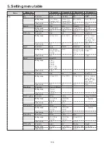
Page 116: ...nge 0 0 to 359 9 0 0 to 100 0 0 0 to 108 0 White Yellow Cyan Green Magenta Red Blue Black Default value 0 0 0 0 100 0 White WIPE Position Parameter X Pos Y Pos Copy To Key Setting range 100 00 to 100 00 100 00 to 100 00 Execute Default value 0 00 0 00 SQ Position Parameter X Pos Y Pos Copy To Key Setting range 100 00 to 100 00 100 00 to 100 00 Execute Default value 0 00 0 00 Modify Parameter Trim ...

Page 117: ...e Sine Saw 0 to 100 180 0 to 180 0 0 0 to 360 0 Default value Sine 0 0 0 0 0 CBGD1 Move Parameter Move Speed Setting range Off Roll Rotation 50 0 to 50 0 Default value Off 1 0 CBGD2 Main Parameter Hue Sat Lum Load Setting range 0 0 to 359 9 0 0 to 100 0 0 0 to 108 0 White Yellow Cyan Green Magenta Red Blue Black Default value 0 0 100 0 100 0 Red CBGD2 Sub Parameter Hue Sat Lum Load Setting range 0...

Page 118: ...315 25 50 75 100 Default value Off 2 0 100 Edge2 Parameter Edge Fill Setting range Color CBGD1 CBGD2 Still1 Still2 Clip1 Clip2 Default value Color Edge Color Parameter Hue Sat Lum Load Setting range 0 0 to 359 9 0 0 to 100 0 0 0 to 108 0 White Yellow Cyan Green Magenta Red Blue Black Default value 0 0 0 0 0 0 Black Transition Parameter Keyout Pattern Setting range Normal Reverse Default value Norm...

Page 119: ...inP2 Key PinP1 PinP2 Key PinP1 PinP2 Default value Key PinP1 PinP2 Chroma Key Auto Compute Parameter Auto Compute Reset Setting range Execute Execute Default value Adjust Parameter Narrow Phase Setting range Off 0 5 1 0 1 5 4 0 to 4 0 Default value Off 0 0 Sample Parameter View Mode Undo Setting range Composite Matte Proc FG FG Select BG Color Clean BG Noise Clean FG Noise Spill Sponge Spill Spill...

Page 120: ...hite Yellow Cyan Green Magenta Red Blue Black Default value 0 0 0 0 100 0 White Position Parameter X Pos Y Pos Size Setting range 100 00 to 100 00 100 00 to 100 00 0 00 to 100 00 Default value 0 00 0 00 25 00 Trim Parameter Trim Manual Setting range Off 4 3 Manual Fixed to Off when a setting other than Square has been selected for the Shape item of the PinP sub menu Free Pair Default value Off Fre...

Page 121: ...hite Yellow Cyan Green Magenta Red Blue Black Default value 0 0 0 0 100 0 White Position Parameter X Pos Y Pos Size Setting range 100 00 to 100 00 100 00 to 100 00 0 00 to 100 00 Default value 0 00 0 00 25 00 Trim Parameter Trim Manual Setting range Off 4 3 Manual Fixed to Off when a setting other than Square has been selected for the Shape item of the PinP sub menu Free Pair Default value Off Fre...

Page 122: ...ta Red Blue Black Default value 0 0 0 0 100 0 White Edge1 Parameter Type Width Direction Density Setting range Off Border Drop Shadow Outline 0 to 4 0 45 90 135 180 225 270 315 25 50 75 100 Default value Off 2 0 100 Edge2 Parameter Edge Fill Setting range Color CBGD1 CBGD2 Still1 Still2 Clip1 Clip2 Default value Color Edge Color Parameter Hue Sat Lum Load Setting range 0 0 to 359 9 0 0 to 100 0 0 ...

Page 123: ...X1 BUS Trans Parameter TransTime Sec Frame Transition Setting range 0 to 33 When 59 94 Hz is selected 0 to 999 Enable Disable Default value 1 0 Disable PinP1 BUS Trans Parameter TransTime Sec Frame Transition Setting range 0 to 33 When 59 94 Hz is selected 0 to 999 Enable Disable Default value 1 0 Disable PinP2 BUS Trans Parameter TransTime Sec Frame Transition Setting range 0 to 33 When 59 94 Hz ...

Page 124: ...n Off Default value 00s01f 00s01f On On Rec1 Parameter Preview V Source Key Enable Review Setting range On Off AUX1 to 4 On Off On Off Default value Off AUX1 On On Rec2 Parameter Loop Quality Limit s Limit f Setting range On Off High Standard 0 to 20 When 59 94i is selected 0 to 600 Default value Off Standard 20 0 Clip1 Play Mode Parameter Mode Reverse Variable Freeze Setting range Lead Last Loop ...

Page 125: ...Default value Display only Shot Memory Store Select Parameter BKGD KEY PinP1 PinP2 Setting range On Off On Off On Off On Off Default value On On On On Recall Select Parameter BKGD KEY PinP1 PinP2 Setting range On Off On Off On Off On Off Default value On On On On XPT Disable Parameter BKGD KEY PinP1 PinP2 Setting range On Off On Off On Off On Off Default value Off Off Off Off Register Parameter Pa...

Page 126: ...lay Mode Setting range Once Loop Default value Once Store Select Parameter BKGD KEY PinP1 PinP2 Setting range On Off On Off On Off On Off Default value On On On On Recall Select Parameter BKGD KEY PinP1 PinP2 Setting range On Off On Off On Off On Off Default value On On On On XPT Disable Parameter BKGD KEY PinP1 PinP2 Setting range On Off On Off On Off On Off Default value Off Off Off Off Register...

Page 127: ...2Signal Setting range The setting range is the same as for the XPT Assign 1 6 sub menu Default value SDI IN8 DVI IN IN A1 None XPT Assign 4 6 Parameter XPT13Signal XPT14Signal XPT15Signal XPT16Signal Setting range The setting range is the same as for the XPT Assign 1 6 sub menu Default value IN A2 IN B1 IN B2 CBAR XPT Assign 5 6 Parameter XPT17Signal XPT18Signal XPT19Signal XPT20Signal Setting ran...

Page 128: ...ng range The setting range is the same as for the MV Pattern 1 4 sub menu Default value SDI IN3 SDI IN4 SDI IN5 SDI IN6 MV Pattern 3 4 Parameter Pos9Signal Pos10Signal Pos11Signal Pos12Signal Setting range The setting range is the same as for the MV Pattern 1 4 sub menu Default value SDI IN7 SDI IN8 DVI IN Still1V MV Pattern 4 4 Parameter Pos13Signal Pos14Signal Pos15Signal Pos16Signal Setting ran...

Page 129: ...ame Off Name Parameter Type Name Setting range Default User Default value Default Up Converter1 Parameter Scale Move Detect Sharp Size SDI IN5 to SDI IN8 IN A1 IN A2 IN B1 and IN B2 only Setting range Squeeze Edge Crop Letter Box 1 to 5 1 to 5 100 to 110 Default value Squeeze 3 3 100 Up Converter2 Parameter Edge Crop Pos Limiter SDI IN5 to SDI IN8 IN A1 IN A2 IN B1 and IN B2 only Setting range Cen...

Page 130: ...ng range Center Right Left Off 108 104 100 Default value Center Off Video Process Parameter Gain Setting range 30 to 30 Default value 0 Input DVI X DVI IN IN A1 IN A2 IN B1 or IN B2 is displayed in the X part The material name up to 10 characters is displayed in the part Freeze Parameter Select Freeze Setting range Frame Field On Off Default value Frame Off Name Parameter Type Name Setting range D...

Page 131: ...n Up Convert Freeze Parameter Select Freeze Setting range Frame Field On Off Default value Frame Off Name Parameter Type Name Setting range Default User Default value Default Up Converter1 Parameter Scale Move Detect Sharp Size Setting range Squeeze Edge Crop Letter Box 1 to 5 1 to 5 100 to 110 Default value Squeeze 3 3 100 Up Converter2 Parameter Edge Crop Pos Limiter Setting range Center Right L...

Page 132: ... Down Convert Down Convert takes effect when AV HS04M7 is connected Default value PGM OUT1 PVW OUT2 AUX1 OUT3 AUX2 OUT4 AUX3 OUT5 AUX1 OUTA1 AUX2 OUTA2 AUX3 OUTB1 AUX4 OUTB2 Normal Down Converter Parameter Scale Delay Sharp Enabled when the AV HS04M7 option board has been connected Setting range Squeeze Edge Crop Letter Box 90H 75H 1F 1 to 5 Default value Squeeze 90H 75H 3 Output Analog Y OUT A1 O...

Page 133: ... 1080 59 94p 720 59 94p 720 50p 1080 50p 1080 50i Fit V Fit H Full Fullx80 Fullx90 Default value Auto Full Output DVI I Y OUT A1 or OUT B1 is displayed in the Y part It takes effect when the AV HS04M5 board has been connected Assign Parameter Source Move Detect Setting range PGM PVW CLN AUX1 to 4 MV Key Out MEM PVW Proc FG 1 to 5 Default value AUX1 OUTA1 AUX3 OUTB1 3 DVI Output Parameter Mode Size...

Page 134: ...Minimum LCD BL Parameter Light Adjust Setting range On Off 60 120 180 80 to 150 Default value On 100 Button Illumination Parameter Illumination Adjust Setting range On Off 80 to 150 Default value On 100 WFM Parameter Style Mode Setting range Parade Overlay YPbPr RGB Y Default value Parade YPbPr Vector Parameter Bar Target Setting range 75 100 Default value 100 User Button1 Parameter User1 User2 Us...

Page 135: ... DSK Trans PinP1Trans PinP2Trans FTB Trans RED Tly1 to 13 GRN Tly1 to 13 AUX Tly1 to 13 Event MEM No Assign Default value No Assign No Assign No Assign No Assign GPI Out Port 2 5 Parameter Port5Assign Port6Assign Port7Assign Port8Assign Setting range The setting range is the same as for the GPI Out Port 1 5 sub menu Default value No Assign No Assign No Assign No Assign GPI Out Port 3 5 Parameter P...

Page 136: ... Phase Setting range 0H 1H The setting range differs from one format to another 1080 59 94i 1100 to 1099 1080 50i 1320 to 1319 1080 24PsF 1375 to 1374 1080 23 98PsF 1375 to 1374 720 59 94p 825 to 824 720 50p 990 to 989 480 59 94i 429 to 428 576 50i 432 to 431 100 to 100 Default value 0H 0 0 Reference Parameter Sync BB Setup Gen Lock Setting range BB BB Advanced Tri level sync Internal 0IRE 7 5IRE ...

Page 137: ...arameter Year Month Day Set Setting range 2011 to 2035 1 to 12 1 to 31 Execute Default value Time Parameter Hour Minute Second Set Setting range 0 to 23 0 to 59 0 to 59 Execute Default value Main Version Parameter System Version Module Type Select Version Setting range Version number Soft FPGA Soft Main1 Main2 BKGD KEY PinP DSK TIME Plugin VMEM Memory XPT MV Input Output Config System BKGDPat XPTS...

Page 138: ...to adjust the density of the key signals Dot by Dot This treats images as actual size 1 images With PinP it allows SD images to be combined with HD images with no accompanying deterioration in the images themselves Down Converter This is the function that converts material in the HD format into the SD format DSK Downstream Key This refers to the key combination process which is performed at the en...

Page 139: ... by overlapping one image with the next It is also referred to as dissolve Multi View Display This function combines multiple materials and displays them on one screen PGM PVW and the input material can be previewed at the same time on a single screen PinP Picture in Picture This function combines a sub screen image with the background image PVW Preview The function for checking ahead of time the ...

Page 140: ... top bottom left and or right of the images which are combined using the PinP function Up Converter This is the function that converts material in the SD format into the HD format which yields a high resolution Video Memory This is the memory in which the images still images and moving images with key signals can be stored Wipe A video effect in which one image is gradually replaced by another as ...

Page 141: ...I Out Port 5 5 135 GPI Out Setting 135 Key Signal Coupling 135 Latency 134 LCD BL 134 Operate 134 System Menu 135 User Button1 134 User Button2 134 Vector 134 WFM 134 D M M DSK 122 Adjust 122 DSK 122 Edge1 122 Edge2 122 Edge Color 122 Fill Matt 122 Mask 122 Mask Adjust 122 E M M Event Memory 126 Event Duration 126 Mark 126 MEM PVW 126 Path 126 Play 126 Recall Select 126 Register 126 Store Select 1...

Page 142: ...32 M M Output DVI D 133 Assign 133 DVI Output 133 M M Output DVI I 133 Assign 133 DVI Output 133 M M Output SDI 132 Assign 132 Down Converter 132 P M M PinP1 120 Border 120 Border Color 120 PinP 120 Position 120 Sync 120 Trim 120 Trim Adjust 120 M M PinP2 121 Border 121 Border Color 121 PinP 121 Position 121 Sync 121 Trim 121 Trim Adjust 121 M M Plug in 123 S M M SD Card 125 Card Information 125 F...

Page 143: ...BUS Trans 123 V M M Video Memory 124 Clip1 Play Mode 124 Clip2 Play Mode 124 Memory 124 Rec1 124 Rec2 124 Trans Sync 124 Video Memory1 124 Video Memory2 124 Video Memory3 124 X M M XPT 127 XPT Assign 1 6 127 XPT Assign 2 6 127 XPT Assign 3 6 127 XPT Assign 4 6 127 XPT Assign 5 6 127 XPT Assign 6 6 127 XPT Setting 127 XPT Switch 127 Index ...

Page 144: ...Web Site http panasonic net Panasonic Corporation 2011 ...

Reviews: