background image

– 28 –

Chapter 3 Preparation — Power supply

Standard charging time and recording time

Battery parts number

Voltage/capacity (minimum)

Charging time

Continuous shootable time

AG-VBR59 (supplied/optional)

7.28 V/5900 mAh

Approx. 3 hours 20 minutes

Approx. 2 hours 50 minutes

AG-VBR89 (optional)

7.28 V/8850 mAh

Approx. 4 hours

Approx. 4 hours 15 minutes

AG-VBR118 (optional)

7.28 V/11800 mAh

Approx. 4 hours 40 minutes

Approx. 5 hours 40 minutes

VW-VBD58 (optional)

7.2 V/5800 mAh

Approx. 5 hours 20 minutes

Approx. 2 hours 40 minutes


f

The charging time is the time when charged using the supplied battery charger.


f

The charging time is the time when the operating ambient temperature is 25 °C and operating relative humidity is 60%. At other temperature and 
humidity the charging time may take longer.


f

The charging time is the time to charge when the charging capacity of the battery is used up. The charging time or the continuous recordable time 
differs depending on the use condition such as high or low temperature.


f

The continuous recordable time is the time when the camera is used in following condition. If you use the camera in other conditions, continuous 
shootable time will shorten.


-

Condition where the LCD monitor and the grip are mounted with the factory default menu settings.


-

Condition where the cable is not connected to the external input/output terminal

@

@

NOTE


t

Battery is warm after using or after charging, but this is not a malfunction.


t

The battery can be charged with the battery charger AG-B23 (DE-A88) (optional), but it will take longer to charge.

Checking the remaining battery level

The remaining battery level can be checked with the power supply status display on the LCD monitor or the indicator on the supplied battery.

Checking the remaining battery level with the LCD monitor

The battery status display will change as 


 while the remaining battery level gets lower. It will flash in red when 

the remaining battery level is zero.

@

@

NOTE


t

The power supply status display may not be displayed depending on the setting in the menu.


t

Repair or copy of the clip, or update of the firmware is not possible when it is flashing in red.

Checking the remaining battery level with the battery


f

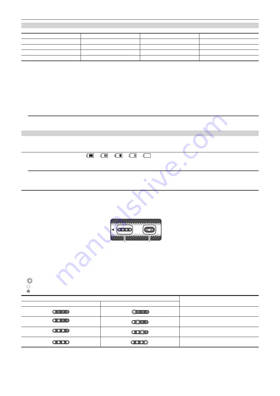
The remaining battery level can be checked with the indicator display by pressing the <CHECK> button on the battery when it is not charging.


-

The remaining battery level is a rough indication.


-

The indicator will not illuminate even if the <CHECK> button is pressed when the remaining battery level is zero. Charge the battery.


f

The progress of the charging is notified by the flashing position of the indicator while the battery is charging.
Once the charging is completed, the indicator turns off.

CHECK

100

%

0

1

2

1  Indicator
2  <CHECK> button


r

Display of the indicator


f

The color and illuminate/flashing status of the indicator indicated by the icon in the table are as follows.


-

: Flashing in green


-

: Illuminated in green


-

: Off

Indicator display

Remaining battery level/charging progress

When checking the remaining battery level

Charging

0% - 25%

25% - 50%

50% - 75%

75% - 100%


f

Display of the indicator is a rough indication. If the battery is mounted to the camera or the battery charger, check the remaining level on the device the 
battery is mounted to. The remaining level may differ from the one displayed with the indicator on the battery.

Summary of Contents for AU-EVA1E

Page 1: ...era Recorder Before using this product be sure to read Read this first pages 2 to 5 Before operating this product please read the instructions carefully and save this manual for future use ENGLISH EJ DVQP1564ZA W1017HM0 YI Model No AU EVA1E ...

Page 2: ... excessive heat such as sunshine fire or the like For Battery Pack Use specified charger Replace only with same or specified type CAUTION To reduce the risk of fire or electric shock and annoying interference use the recommended accessories only CAUTION In order to maintain adequate ventilation do not install or place this unit in a bookcase built in cabinet or any other confined space To prevent ...

Page 3: ... and that it is approved by ASTA or BSI to BS1362 Check for the ASTA mark or the BSI mark on the body of the fuse If the plug contains a removable fuse cover you must ensure that it is refitted when the fuse is replaced If you lose the fuse cover the plug must not be used until a replacement cover is obtained A replacement fuse cover can be purchased from your local Panasonic Dealer How to replace...

Page 4: ...start quickly at any time but a Power Management function will cause an increase in the time taken to resume from Stand by mode It has been found that counterfeit battery packs which look very similar to the genuine product are made available to purchase in some markets Some of these battery packs are not adequately protected with internal protection to meet the requirements of appropriate safety ...

Page 5: ...ery Lithium Battery For the removal of the battery for disposal at the end of its service life please consult your dealer Battery Charger AC Adaptor Disconnect the AC mains plug from the AC mains socket when not in use r r The symbols on this product including the accessories represent the following d AC e DC Class II equipment The construction of the product is double insulated ...

Page 6: ... Alliance f f WPATM and WPA2TM are trademark of Wi Fi Alliance f f All other names company names product names etc contained in this instruction manual are trademarks or registered trademarks of their respective owners License f f This product is licensed under the AVC Patent Portfolio License All other acts are not licensed except private use for personal and non profit purposes such as what are ...

Page 7: ... screen 61 HOME screen 61 INFO screen 63 VIEW screen 63 Thumbnail screen 63 Basic operation of the menu 64 Configuration of the menu 64 Displaying the menu 65 Operating the menu 66 Initializing the menu 67 Menu setting contents 68 THUMBNAIL menu 68 SYSTEM SETTINGS menu 68 CAMERA SETTINGS menu 74 SCENE FILE SETTINGS menu 78 REC SETTINGS menu 82 AUDIO SETTINGS menu 84 OUTPUT SETTINGS menu 86 FILE me...

Page 8: ...me and the password 154 Deleting the user account 154 Connecting the camera and the iPad Android terminal 155 Direct connection DIRECT 155 Connecting to the wireless access point INFRA SELECT INFRA MANUAL 155 Chapter 9 Notes 158 Frequently asked questions 159 Power supply 159 Battery 159 Battery charger 159 SD card 159 Shooting 159 Editing 159 Playback 160 Others 160 Warning system 161 Cases indic...

Page 9: ...Before using the camera read this chapter Chapter 1 Overview ...

Page 10: ...rt automatically after the battery reaches chargeable temperature f f If the charging lamp continues to flash even when the battery is at its optimal temperature the battery or battery charger may be damaged Consult the dealer f f Noise may be generated in radio when the camera is used close to a radio especially when receiving AM Keep a distance of 1 m or more when using f f Oscillating sound may...

Page 11: ...lens toward the sun Doing so might damage the components inside r r Caution regarding laser beams The MOS sensor may be damaged if the MOS sensor is subjected to light from a laser beam Take sufficient care to prevent laser beams from striking the lens when shooting in an environment where laser devices are used r r Note the following points f f If you prepare to record important images always sho...

Page 12: ...uct 1 This product includes software licensed under GNU General Public License GPL and GNU Lesser General Public License LGPL and customers are hereby notified that they have rights to obtain re engineer and redistribute the source code of these software 2 This product includes software licensed under MIT License 3 This product includes software developed by the OpenSSL Project for use in the Open...

Page 13: ...hone holder adaptor page 38 Grip page 32 f f Already mounted to the camera Grip belt page 32 f f Already mounted to the grip LCD monitor page 35 LCD monitor hood page 35 f f Already mounted to the LCD monitor LCD monitor mounting attachment page 35 f f Already mounted to the LCD monitor Handle page 31 f f Already mounted to the camera Mount cap page 39 f f Already mounted to the camera NOTE t t Ap...

Page 14: ... AG VBR89 7 28 V 8850 mAh AG VBR118 7 28 V 11800 mAh VW VBD58 7 2 V 5800 mAh Attaching and removing the battery Battery charger AG BRD50 Product compatible to included battery charger AG B23 Charging the battery SD card Visit the support desk at the website Preparing the SD card For the latest information not included in these Operating Instructions refer to the support desk at the following websi...

Page 15: ...K 120P 2 When the frame rate exceeding 120P internal recording eight bit 4 2 0 4K crop size 3 Supports firmware update Recording to the memory card SD card Recording in following types is possible f f 4K UHD 2K FHD recording 4 2 0 8 bits MOV recording 4 2 2 10 bits MOV recording f f AVCHD recording f f Variable frame rate recording Supports 120fps 240fps recording in 2K FHD f f Simultaneous record...

Page 16: ...This chapter describes the names functions and operations of parts on the camera Chapter 2 Description of Parts ...

Page 17: ...e cable 4 Microphone holder mounting section Mounts the included microphone holder adaptor and the microphone holder 5 LCD monitor cable clamp Fixes the cable for the LCD monitor unit 6 Focus hook Indicates the position of the image surface plane of the image sensor 7 Grip mounting section Mounts the included grip 8 LCD terminal Connects the cable for the LCD monitor unit 9 REMOTE terminal Connect...

Page 18: ... the iris of the EF lens Turn upward Controls toward closing Turn downward Controls toward opening Press Switches between AUTO MANU 6 MENU button Displays the menu Pressing the MENU button while the menu is displayed closes the menu 7 AWB USER 6 button Adjusts the white balance Also this is also used as the USER button USER6 8 Accessory mounting section The included LCD monitor mounting attachment...

Page 19: ...witch Sets the button and switch to disable the operation in the SYSTEM SETTINGS menu SIDE LOCK 19 WB USER ISO dB switch Use by switching between WB white balance USER USER button ISO dB gain adjustment functions The selected function is operated with the multidial 20 Multidial Moves selects and sets the menu while the menu is displayed Also operates the selected function with the WB USER ISO dB s...

Page 20: ...ndicates the access status for recording and playback of the SD card inserted in the card slot 1 To flash the lamp or not can be set in the menu 2 Card slot 1 Slot for SD card 3 Card slot 2 Slot for SD card 4 Card 2 access lamp Indicates the access status for recording and playback of the SD card inserted in the card slot 2 To flash the lamp or not can be set in the menu 5 SLOT SEL USER 7 button S...

Page 21: ...supply 17 TC IN OUT terminal Connects to an external equipment and output input a time code Inputs the standard time code when locking the time code with an external equipment Input and output are set in the REC SETTINGS menu TC TC IN OUT SEL Top side 2 1 1 2 3 4 1 Shoulder strap mounting section Mounts the included shoulder strap page 37 2 Accessory shoe Attaches the video light 3 Accessory mount...

Page 22: ... 22 Chapter 2 Description of Parts Camera Bottom side 1 1 Tripod holes Attach the tripod f f Mounting hole size 1 4 20 UNC screw length 5 5 mm or shorter 3 8 16 UNC screw length 5 5 mm or shorter ...

Page 23: ...o the HOME screen that is the starting point of the operation the VIEW screen that displays the recording image the INFO screen that displays the information of the camera etc can be displayed Supports the touch operation 3 LCD monitor mounting attachment Mounts to the LCD monitor mounting section of the handle etc 4 MIRROR switch Inverts the VIEW screen vertically or both vertically and horizonta...

Page 24: ... REC button Starts or stops the recording 3 MENU button Displays the menu Pressing the MENU button while the menu is displayed closes the menu 4 USER 9 button Can be used as the USER button USER9 while displaying the VIEW screen 5 Grip mounting section Mounts to the grip mounting section of the camera 6 Grip rotation lever Pulling to UNLOCK side allows to adjust the position of the grip by rotatin...

Page 25: ... finger Do not touch the LCD monitor with a pointed hard object such as a ball point pen r r Touching An operation to press and release the LCD monitor An item or icon can be selected or an item can be executed f f To select an icon touch the center of the icon f f It will not operate while touching a different location of the LCD monitor r r Sliding An operation to move a finger while touching th...

Page 26: ...Before you use the camera mount the battery following the procedures in this chapter The mounting of accessories is also described in this chapter Chapter 3 Preparation ...

Page 27: ...ted the CHARGE1 CHARGE2 lamp charging lamp will turn off Slide the battery and remove it r r Display of the CHARGE1 CHARGE2 lamp CHARGE1 CHARGE2 lamp The CHARGE1 CHARGE2 lamp charging lamp of the supplied battery charger indicates the charging status as follows Display of the CHARGE1 CHARGE2 lamp Charging status Green illuminated Quick charging Orange illuminated Normal charging Orange flashing St...

Page 28: ...ing the remaining battery level The remaining battery level can be checked with the power supply status display on the LCD monitor or the indicator on the supplied battery Checking the remaining battery level with the LCD monitor The battery status display will change as while the remaining battery level gets lower It will flash in red when the remaining battery level is zero NOTE t t The power su...

Page 29: ...unting section of the camera and mount it by sliding it downward f f Press in the battery until it clicks and gets locked Removing the battery Battery release button 1 Set the power switch to standby f f Check that the power lamp is turned off 2 While pressing the battery release button on the camera slide the battery upward and remove it ...

Page 30: ...witch to standby and check that the power lamp is turned off before removing NOTE t t To record with the AC adaptor connected mount the battery in case there is a power outage or disconnection of the power outlet t t The power is consumed even when the power switch is set to standby To prevent power consumption disconnect the AC adaptor from the power outlet when it is not used for a long period o...

Page 31: ... the handle to the accessory mounting holes at the top of the camera body using the handle mounting screws x 2 NOTE t t Use the handle after securely tightening the handle mounting screws x 2 Using without securely tightening them may cause the camera to fall due to handle coming off Removing the handle Remove in the reverse procedure as mounting ...

Page 32: ...section of the grip when inserting into the camera 2 Slowly turn the grip counter clockwise until it clicks Fig 2 3 Connect the grip cable to the REMOTE terminal Fig 3 4 Fix the grip cable with the grip cable clamp Fig 3 NOTE t t If it does not mount correctly perform the mounting from the beginning Do not apply excessive force to the grip and the camera t t Store the grip cable inside the grip ca...

Page 33: ...r to the UNLOCK side 2 Adjust the angle of the grip and return the grip rotation lever at the position to fix The grip is fixed f f The grip can be fixed in 8 different positions r r Adjusting the grip belt The grip belt is already mounted to the grip Cover Belt 1 Open the cover and adjust the length of the belt 2 Replace the cover ...

Page 34: ...ASE button 1 Remove the grip cable from the grip cable clamp 2 Remove the grip cable from the REMOTE terminal 3 While pressing the GRIP RELEASE button on the camera turn the grip clockwise NOTE t t Remove the grip after placing the camera body on a level location such as desk ...

Page 35: ...nitor unit cable to the LCD terminal Fig 2 f f Connect by aligning a of the LCD terminal with s of the LCD monitor unit cable connection terminal f f Connect after confirming that s of the LCD monitor unit cable connection terminal is facing outward 4 Attach the LCD monitor unit cable to the LCD monitor cable clamp Fig 3 r r Adjusting the angle of the LCD monitor The LCD monitor can be turned vert...

Page 36: ...e connection terminal s LCD monitor hood The LCD monitor hood is already mounted to the LCD monitor unit Removing the LCD monitor hood 1 Remove the LCD monitor hood while pushing in your nails into the gaps of the tabs 2 locations at the upper of the LCD monitor hood The LCD monitor hood is removed Opening and closing of the LCD monitor hood NOTE t t Close the LCD monitor hood to protect the LCD m...

Page 37: ...ples at the top of the LCD monitor unit 2 Align the tabs at the bottom of the LCD monitor hood 2 locations to the dimples at the bottom of the LCD monitor unit Attaching the shoulder strap Mount the supplied shoulder strap to the shoulder strap mounting section 20 mm or more 20 mm or more NOTE t t Make sure that the shoulder strap is securely attached ...

Page 38: ...ophone holder adaptor to the microphone mounting section of the camera Fig 1 f f Tighten the screw included with the microphone holder adaptor 2 Mount the included microphone holder to the microphone holder adaptor using the microphone holder screws x 2 Fig 2 3 Mount the external microphone and tighten the screw on the microphone holder Fig 3 4 Connect the microphone cable to the AUDIO INPUT 1 ter...

Page 39: ...ned off 2 Remove the mount cap Fig 1 f f Turn the mount cap counter clockwise until the marking on the mount cap is at the top and remove the camera body 3 Insert the lens into the EF lens mount with the mark on the lens red dot facing up Fig 2 4 Turn the lens clockwise until it clicks Fig 3 Removing the lens Lens lock unlock button 1 Set the power switch to standby f f Check that the power lamp i...

Page 40: ...Attach the mount cap to the EF lens mount Use the mount cap after removing dirt and dust Attaching a tripod The tripod attachment holes accept 1 4 20 UNC and 3 8 16 UNC screws Use the hole that matches the diameter of the clamping screw on the tripod NOTE t t Use a tripod in safe locations t t The depth of the tripod attachment hole is 5 5 mm Do not over tighten the tripod screw when mounting the ...

Page 41: ...Set the time zone date and time NOTE t t The internal battery rechargeable battery will discharge The setting for date time may be initialized when the camera is not turned on for approximately two months Set the date time again after charging the built in battery page 42 t t The power lamp will not illuminate or flash when the SYSTEM SETTINGS menu LED FAN POWER LED OFF is set However it will illu...

Page 42: ...tandby 2 Connect the AC adaptor to the camera For details on connection of the AC adaptor refer to Using the AC adaptor 3 Leave the camera for approx four hours The built in battery will be charged f f Check the date time setting and the time code after charging f f Select DIAGNOSTICS in the INFO screen and set the date time for the internal clock if INTERNAL CLOCK HAS RESET PLEASE SET TO CORRECT ...

Page 43: ...nds per month Check and reset the time when accurate time is required t t In the AVCHD format clip will be save in 12 30 even selecting 12 45 due to format standards r r Time zone table Time difference Region Time difference Region 00 00 Greenwich 01 00 Central Europe 00 30 01 30 01 00 Azores 02 00 Eastern Europe 01 30 02 30 02 00 Mid Atlantic 03 00 Moscow 02 30 03 30 Tehran 03 00 Buenos Aires 04 ...

Page 44: ...r r When the recording mode is MOV SDXC memory card can be used Recording bit rate or recording function Speed Class Example of card display 200 Mbps Video Speed Class V30 or higher UHS Speed Class 3 or higher 150 Mbps 100 Mbps 2K FHD VFR LongGOP Variable frame rate recording 50 Mbps Video Speed Class V10 or higher UHS Speed Class 1 or higher Speed Class 10 or higher r r When the recording mode is...

Page 45: ...mera page 46 f f All the recorded data will be erased and would not be able to restore when the SD card is formatted Card slot 1 Card 1 access lamp Card slot 2 Card 2 access lamp Card slot cover Fig 1 Fig 2 1 Open the card slot cover Fig 1 2 Insert the SD card into the card slot Fig 2 f f The card slot 1 and the card slot 2 can each insert one SD card f f Insert straight in with the label facing l...

Page 46: ...g is stopped once when the recording time reaches ten hours and recording is automatically resumed after few seconds Image and audio during the pause will not be recorded This includes the case of special recording such as variable frame rate recording or relay recording When performing high speed shooting with the variable frame rate recording the recording time will be shorter than 10 hours depe...

Page 47: ...der structure as shown in the figure If such information is changed or deleted even partially an error may occur such as that the data may not be recognized as the AVCHD data or the SD card may not be used on the AVCHD device NOTE t t Do not erase the folder or file in the SD card with a PC It may make it impossible to read on the camera t t An error may occur such as that the SD card will not be ...

Page 48: ... AU V35LT1G etc CINE format Clip can be managed in the same manner as VARICAM B 0 0 2 C 0 1 0 _ 1 7 0 9 1 8 _ E 1 2 5 MOV 2 1 3 4 5 1 CAM INDEX One character from upper case A to Z f f An INDEX assigned to each camera Set with the REC SETTINGS menu CLIP NAME CAM INDEX 2 REEL number 001 999 f f A number assigned for each SD card The REEL COUNT stored in the volume label of the SD card is assigned 3...

Page 49: ...fter recording r r Date time real time f f The internal clock will be the reference for the measurement of the free run time code while the power is set to standby time of the user bits and date data Also it will be the reference for the file generation time and file name when the clip is recorded NOTE t t The display in the VIEW screen and the HOME screen is switched with the REC SETTINGS menu TC...

Page 50: ...es the time code in the drop frame mode NDF Advances the time code in the non drop frame mode 3 Select the REC SETTINGS menu TC SET TC The SET TC screen is displayed 4 Set the time code 5 Confirm the setting value of the time code f f The setting value is confirmed when last two digits are set r r Setting range of time code The range of time code that can be set differs depending on FREQUENCY FREQ...

Page 51: ...de Also enter the time code of the non drop frame for 23 98p 24 00p 25 00p 50 00p and 50 00i NOTE t t Do not slave lock to the externally input time code but automatically advance with internal reference during recording or rec remote controlling of the external recording device The time code value may overlap or drop out after recording or ending rec remote due to performing slave lock to the tim...

Page 52: ...TC IN OUT SEL TC OUT 2 Select the REC SETTINGS menu TC TC OUT REF RECORDING The same time code can be recorded to the video of the same time on two devices r r To match the time code output from the TC IN OUT terminal to the video of the SDI output or the monitor output 1 Select the REC SETTINGS menu TC TC OUT REF SDI OUT NOTE t t TCR is output during playback TCG output during playback is not sup...

Page 53: ...he IR recording REC SW Starts or stops the recording PRE REC Enables disables the pre recording REC CHECK Automatically plays back the last approximately three seconds of the previously shot clip DEL LAST CLIP Deletes the clip last shot SLOT SEL Selects the card slot with the SD card to record inserted Or switches the card slot for the clip to display in the thumbnail screen EXPAND Enables disable...

Page 54: ...lue of the shutter speed can be selected by turning the multidial FPS Enables disables the variable frame rate record function when the multidial is pressed The setting value of the frame rate can be selected by turning the multidial MONITOR VOL The adjustment of the audio level output from the headphones terminal is enabled when the multidial is pressed The level meter for adjusting is displayed ...

Page 55: ... flash when the camera is in the following status When the remaining capacity of the SD card or the remaining battery level is low one time per second The SD card has no more space to record four times per second When a warning such as a system error or a recording abnormality has occurred four times per second NOTE t t The tally lamp will not illuminate or flash when the SYSTEM SETTINGS menu LED ...

Page 56: ...This chapter describes how to operate the screen of this camera how to operate the menu the structure of the menu and details of the menu Chapter 4 Operation ...

Page 57: ...tails of the VIEW screen refer to Screen status display r r INFO button Displays the INFO screen Information of the camera can be confirmed For details of the INFO screen refer to INFO screen r r THUMBNAIL button Displays the thumbnail screen Playback copy delete or protect of a clip can be performed For details of the thumbnail screen refer to Thumbnail operation r r HOME button Displays the HOME...

Page 58: ... is pressed 1 3 4 1 3 3 3 1 2 2 1 4 Thumbnail screen VIEW screen HOME screen INFO screen Clip information 1 HOME button 2 VIEW button 3 THUMBNAIL button 4 INFO button NOTE t t The VIEW screen is displayed when the camera is turned on t t Switches to the VIEW screen automatically when the recording is started t t Pressing the HOME button will switch between the HOME screen and the VIEW screen ...

Page 59: ...d 7 Number of recorded pixels system frequency Displays the number of recording pixels and the system frequency 8 Pre recording status display Displays the re recording status When the REC SETTINGS menu PRE REC ON is set and pre recording is enabled No display When the REC SETTINGS menu PRE REC OFF is set or when pre recording is unable 9 Card slot 1 card slot 2 status display Indicates the insert...

Page 60: ...of the user bits generator Dur Displays the value of the duration 16 Audio level meter Displays the recording level of audio with 18 bars 2 dB steps Displays in red bar when exceeding 0 dB When the variable frame rate recording function is enabled but in a mode that cannot record audio 17 External output terminal output image setting display Displays the output image of the external output termina...

Page 61: ...ted in the HOME screen allowing to select the frame rate f f Select from the previously registered frame rate setting values in f f The frame rate setting value can be added deleted in the CAMERA SETTINGS menu FPS ADD DELETE Maximum of 150 setting values 128 for 25 00p 50 00p can be registered NOTE t t This function cannot be selected when the CAMERA SETTINGS menu FPS VFR SW OFF is set r r VFR dis...

Page 62: ...ter speed f f Select from the previously registered shutter speed setting values in f f The shutter speed setting value can be added deleted in the CAMERA SETTINGS menu SHUTTER ADD deg ADD sec DELETE deg DELETE sec Maximum of 12 setting values can be registered NOTE t t This function cannot be set when the CAMERA SETTINGS menu SHUTTER SW OFF is set EI When EI is selected in the HOME screen the VIE...

Page 63: ... to operating with the multidial and touch operations each item can be selected by pressing the INFO button DIAGNOSTICS Displays the status of the camera such as warning SWITCHES Displays the assignment status of each USER button VERSION Displays the model name serial number and firmware version NETWORK Displays the setting value and connection status of the wireless LAN AUDIO Displays the audio s...

Page 64: ...enu Performs confirmation or deleting of the recording clip This menu can be set when the thumbnail screen is displayed SYSTEM SETTINGS menu Sets the system in general CAMERA SETTINGS menu Sets the basic function of the camera This menu cannot be set when the thumbnail screen is displayed SCENE FILE SETTINGS menu Sets the setting regarding scene file This menu sets the detailed image quality adjus...

Page 65: ...5 2 3 1 Level display Displays the path of the menu to the currently displayed screen 2 Moves the cursor up or down when selected 3 Returns to one level higher from the current menu when selected 4 Menu Moves to one level lower from the current menu or to the setting screen when selected 5 SET Confirms the set value when selected NOTE t t The menu displayed in gray characters cannot be changed ...

Page 66: ...he similar operation if there is next level f f In some menus a screen to set the numeric value is displayed in the VIEW screen Fig 2 f f In some menus a message is displayed if a menu cannot be executed f f To return to one level higher press the EXIT button 3 Select the item to set 1 Turn the multidial to move the cursor to the item to set 2 Press the multidial A check mark is displayed at the l...

Page 67: ...e numeric value is displayed in the VIEW screen To change the numeric value touch and change the setting value f f In some menus a message is displayed if a menu cannot be executed f f The cursor is moved up or down by touching f f To return to one level higher touch 3 Select the item to set f f Touch the item to set A check mark is displayed at the left of the set item f f To return to one level ...

Page 68: ...D card INFORMATION Displays the detailed information of the clip NOTE t t The clip recorded in the MOV format cannot be copied SYSTEM SETTINGS menu Sets the system in general SYSTEM MODE For the combination that can be set refer to Selecting the resolution codec and frame rate for recording video FREQUENCY Sets the system frequency The items that can be set are as follows f f 23 98p 24 00p 25 00p ...

Page 69: ...E5 Sets to setting to perform detailed image quality adjustment with the camera When SCENE1 to SCENE5 is selected the menu setting for the same scene number is enabled in the SCENE FILE SETTINGS menu Factory setting V Log SDI OUT Sets the output image from the SDI OUT terminal f f When MAIN in COLOR SETTINGS is set to V Log V Log Outputs with the same color as the video recorded in the main record...

Page 70: ...signed function is enabled when the VIEW screen is displayed Factory setting SPOT METER USER4 Sets the function to assign to the USER 4 button Factory setting E I S USER5 Sets the function to assign to the USER 5 button Factory setting WFM USER6 Sets the function to assign to the USER 6 button Factory setting AWB USER7 Sets the function to assign to the USER 7 button Factory setting SLOT SEL USER8...

Page 71: ...AIL button is to be locked or not with the LOCK switch LOCK It will be locked UNLOCK It will not be locked Factory setting LOCK HOME Sets if the HOME button is to be locked or not with the LOCK switch LOCK It will be locked UNLOCK It will not be locked Factory setting LOCK ND FILTER Sets if the ND FILTER button is to be locked or not with the LOCK switch LOCK It will be locked UNLOCK It will not b...

Page 72: ...f it is set to OFF FAN SPEED Sets the rotation speed of the fan AUTO It will rotate in slow speed until the specified temperature is reached and then it will rotate in the same speed as FULL when the specified temperature is reached FULL It will always rotate in constant speed Factory setting AUTO LCD BRIGHTNESS Adjusts the brightness of the LCD monitor The items that can be set are as follows f f...

Page 73: ... of the camera VERSION MODEL Displays the product name of the camera SERIAL NO Displays the serial number of the camera VERSION Displays the firmware version of the camera OPERATION TIME TOTAL OPERATION Displays the total operation time IRIS DIAL Displays the total number of upward rotation or downward rotation of the IRIS dial by updating every time it reaches 100 turns T indicates the number SEN...

Page 74: ...re as follows f f ON OFF Factory setting ON MODE Sets the displaying method of the shutter speed sec Displays in time deg Displays in the shutter aperture angle Factory setting deg VALUE deg Selects the aperture angle of the shutter when the display unit in MODE of SHUTTER is set to deg Following values are registered as the factory settings f f HALF SHUTTER 11 5d 22 5d 45 0d 90 0d 120 0d 144 0d 1...

Page 75: ...250 ISO Factory setting 800 ISO 800BASE ISO Sets the value when 800BASE is selected in ISO SELECT of EI The items that can be set are as follows When GAMMA SELECT is set to anything other than VIDEO 200 ISO 250 ISO 320 ISO 400 ISO 500 ISO 640 ISO 800 ISO 1000 ISO 1250 ISO 1600 ISO 2000 ISO When GAMMA SELECT is set to VIDEO 200 ISO 250 ISO 320 ISO 400 ISO 500 ISO 640 ISO 800 ISO 1000 ISO Factory se...

Page 76: ...lected when the CAMERA SETTINGS menu IR SHOOTING ON is set ADD Newly registers the adjustment value of auto white balance The newly registered value can be selected in VALUE of WHITE Maximum of 12 values can be registered It cannot be registered when there are 12 registered already Following values are registered as the factory settings f f 2000K 15000K 10 0GMg 10 0GMg EDIT The currently selected ...

Page 77: ... f ON OFF Factory setting OFF ZOOM POSITION DATA Sets the focal distance of the lens required for the electronic image stabilization AUTO Performs the electronic image stabilization using the focal distance information automatically MANUAL Performs the electronic image stabilization using the focal distance set in ZOOM POSITION VALUE NOTE t t When setting to AUTO an EF lens supporting the acquisit...

Page 78: ...that can be selected are as follows f f YES NO BLACK Adjusts the standard black level M PED Adjusts the standard black level for the entire video The items that can be set are as follows f f 100 100 Factory setting 0 R PED Adjust the standard black level for Rch The items that can be set are as follows f f 100 100 Factory setting 0 G PED Adjust the standard black level for Gch The items that can b...

Page 79: ...ows f f ON OFF Factory setting ON KNEE MODE Sets the knee operation mode D RANGE The dynamic range that can be represented is determined by the value of KNEE SLOPE in KNEE The value of dynamic range that can be represented does not change even when the value of KNEE POINT in KNEE is changed PRESS The compression rate of the signal is determined by the value of KNEE SLOPE in KNEE The value of dynam...

Page 80: ...ets the level of coring against the detail The items that can be set are as follows f f 0 60 Factory setting 0 MASTER LEVEL Sets the level of the detail effect of the whole part The items that can be set are as follows f f 31 31 Factory setting 0 FREQUENCY Sets the thickness of the detail The items that can be set are as follows f f 1 3 Factory setting 1 SKIN DETAIL SKIN DTL1 Selects the skin tone...

Page 81: ... G R Adjusts the linear matrix Green Red The items that can be set are as follows f f 63 63 Factory setting 0 G B Adjusts the linear matrix Green Blue The items that can be set are as follows f f 63 63 Factory setting 0 B R Adjusts the linear matrix Blue Red The items that can be set are as follows f f 63 63 Factory setting 0 B G Adjusts the linear matrix Blue Green The items that can be set are a...

Page 82: ...return to 001 after 999 f f When the SD card is formatted f f When recorded to the SD card where REEL COUNT is not stored in the volume label The items that can be set are as follows f f 001 999 Factory setting 001 NOTE t t This will be stored in the volume label of the SD card but will not be used in the file name when the SYSTEM SETTINGS menu SYSTEM MODE MAIN CODEC is set to AVCHD format 2 SLOTS...

Page 83: ...NDF Uses the non drop frame mode Factory setting NDF UB MODE Selects the user bits mode User bits information is recorded in the clip Also it is output as LTC UB VITC UB of the SDI signal FRAME RATE Selects the image information such as frame rate of the camera USER Selects the user bits set in SET UB TIME Selects the local time hh mm ss DATE Selects the local date and time YY MM DD hh CLIP NAME A...

Page 84: ...at can be set are as follows f f ON OFF Factory setting OFF CH1 LIMITER Enables disables the limiter when the method to adjust the audio input level for audio channel 1 is manual The items that can be set are as follows f f ON OFF Factory setting OFF CH2 LIMITER Enables disables the limiter when the method to adjust the audio input level for audio channel 2 is manual The items that can be set are ...

Page 85: ...hen the audio device is connected and INPUT1 LINE MIC SEL of AUDIO INPUT is set to LINE The items that can be set are as follows f f 4dB 0dB Factory setting 4dB INPUT2 LINE LEVEL Sets the audio input level of the audio device connected to the AUDIO INPUT 2 terminal Enabled when the audio device is connected and INPUT2 LINE MIC SEL of AUDIO INPUT is set to LINE The items that can be set are as foll...

Page 86: ...ing system error is fixed to MED OUTPUT SETTINGS menu Sets the display content or output format of the video SDI OUT OUTPUT SW Enables disables the output from the SDI OUT terminal ON Outputs the video OFF Does not output the video Factory setting ON SIGNAL SEL Sets the output from the SDI OUT terminal SDI Outputs the signal set in OUT FORMAT of SDI OUT LCD 1080p Outputs the video displayed on the...

Page 87: ...or not in the output from the SDI OUT terminal The items that can be set are as follows f f ON OFF Factory setting ON NOTE t t Even if MENU DISP is set to OFF the menu is displayed in the output from the SDI OUT terminal during the thumbnail screen HDMI OUT OUT FORMAT Selects the signal to be output from the HDMI terminal The items that can be selected differ depending on the setting in the SYSTEM...

Page 88: ...SETTINGS menu SDI OUT INDICATOR DISP and the OUTPUT SETTINGS menu HDMI OUT INDICATOR DISP to ON For content of display refer to Screen status display CLIP NAME Displays hides file name of the clip to record Displays maximum of 8 characters from beginning The items that can be set are as follows f f ON OFF Factory setting ON PIXEL FREQ Displays hides the number of recorded pixels and system frequen...

Page 89: ...ng ON AUDIO LEVEL METER Displays hides the audio level meter The items that can be set are as follows f f ON OFF Factory setting ON FPS Displays hides the setting in the CAMERA SETTINGS menu FPS The items that can be set are as follows f f ON OFF Factory setting ON SHUTTER Displays hides the shutter speed The items that can be set are as follows f f ON OFF Factory setting ON EI Displays hides EXPO...

Page 90: ...Open center small OFF Does not display Factory setting 1 SAFETY MARKER Selects the type of frame for the safety zone marker 1 Box 2 Corners OFF Does not display Factory setting OFF SAFETY AREA Sets the size of the safety zone marker The items that can be set are as follows f f 71 6 80 90 95 Factory setting 90 FRAME MARKER Sets the aspect ratio of the frame marker The frame marker is not displayed ...

Page 91: ...AT Displays hides recording codec of the main recorder The items that can be set are as follows f f ON OFF Factory setting ON SLOT1 2 STATUS Displays hides the status of the card slot and remaining recordable capacity The items that can be set are as follows f f ON OFF Factory setting ON 2 SLOTS FUNC Displays hides the setting in the REC SETTINGS menu 2 SLOTS FUNC The items that can be set are as ...

Page 92: ...s f f ON OFF Factory setting ON ND FILTER Displays hides the ND filter transmittance The items that can be set are as follows f f ON OFF Factory setting ON E I S D ZOOM Displays hides the setting in E I S or D ZOOM The items that can be set are as follows f f ON OFF Factory setting ON WLAN Displays hides the connection status display of the wireless LAN The items that can be set are as follows f f...

Page 93: ...ides the marker against the playback video output from the LCD terminal The items that can be set are as follows f f ON OFF Factory setting OFF LCD FOCUS ASSIST EXPAND MODE Sets the enlargement display function mode 10SEC Disables the enlarged display function after ten seconds have elapsed HOLD The enlarged display function is enabled until the USER button assigned with EXPAND is pressed again UN...

Page 94: ...ZEBRA Sets if the zebra signal is superimposed or not to the output from the LCD terminal The items that can be set are as follows f f ON OFF Factory setting OFF ZEBRA1 DETECT Sets the detection level of zebra pattern 1 The items that can be set are as follows f f 0 109 Factory setting 80 ZEBRA2 DETECT Sets the detection level of zebra pattern 2 The items that can be set are as follows f f 0 109 F...

Page 95: ...r bars are displayed The reference level varies depending on the setting in the AUDIO SETTINGS menu AUDIO CH SETTINGS HEAD ROOM The items that can be set are as follows f f ON OFF Factory setting ON FILE menu Saves and reads the setting data For saving and loading target refer to Target items for scene file setup file initialization For details of saving and loading refer to Handling setting data ...

Page 96: ... manually Factory setting DIRECT SSID Enters or displays the network name of the camera SSID Factory setting AU EVA1 BAND Switches between two communication methods 2 4GHz or 5GHz when NETWORK PROPERTY TYPE DIRECT is selected The items that can be set are as follows f f 2 4GHz 5GHz Factory setting 2 4GHz CHANNEL 2 4GHz Sets the channel to be used when connected to the wireless LAN with following i...

Page 97: ... 0 0 t t Default gateway setting is invalid when NETWORK PROPERTY TYPE DIRECT is selected PRIMARY DNS Sets the primary DNS server in NETWORK PROPERTY when INFRA SELECT or INFRA MANUAL in TYPE is selected and OFF is selected for DHCP Factory setting 0 0 0 0 NOTE t t When NETWORK PROPERTY TYPE DIRECT is selected settings in primary DNS server is invalid SECONDARY DNS Sets the secondary DNS server in...

Page 98: ... VIDEO HLG OFF OFF OFF B GAMMA RANGE 1 1 1 KNEE KNEE SW Enabled when GAMMA is set to VIDEO Enabled when GAMMA is set to VIDEO ON ON Enabled when GAMMA is set to VIDEO KNEE MODE D RANGE D RANGE KNEE POINT 90 93 KNEE SLOPE 100 100 HLG KNEE KNEE SW Enabled when GAMMA is set to HLG Enabled when GAMMA is set to HLG Enabled when GAMMA is set to HLG Enabled when GAMMA is set to HLG OFF KNEE POINT 55 KNEE...

Page 99: ...0 0 P4 SAT 0 0 0 0 0 P4 PHASE 0 0 0 0 0 P5 SAT 0 0 0 0 0 P5 PHASE 0 0 0 0 0 G SAT 0 0 0 0 0 G PHASE 0 0 0 0 0 P6 SAT 0 0 0 0 0 P6 PHASE 0 0 0 0 0 Cy SAT 0 0 0 0 0 Cy PHASE 0 0 0 0 0 P7 SAT 0 0 0 0 0 P7 PHASE 0 0 0 0 0 B SAT 0 0 0 0 0 B PHASE 0 0 0 0 0 P8 SAT 0 0 0 0 0 P8 PHASE 0 0 0 0 0 Mg SAT 0 0 0 0 0 Mg PHASE 0 0 0 0 0 P9 SAT 0 0 0 0 0 P9 PHASE 0 0 0 0 0 P10 SAT 0 0 0 0 0 P10 PHASE 0 0 0 0 0 ...

Page 100: ...l l RESUME PLAY l l CLIP PROTECT DELETE COPY INFORMATION SYSTEM SETTINGS menu Item SCENE SETUP INITIALIZE SYSTEM MODE FREQUENCY l l SENSOR MODE l l MAIN PIXEL l l MAIN CODEC l l COLOR SETTINGS MAIN l l SDI OUT l l HDMI OUT l l LCD OUT l l USER SWITCHES USER1 l l USER2 l l USER3 l l USER4 l l USER5 l l USER6 l l USER7 l l USER8 l l USER9 l l USER TOGGLE l l SIDE LOCK REC l l USER1 l l USER2 l l USE...

Page 101: ...W l l MODE l l VALUE deg l l ADD deg EDIT deg DELETE deg VALUE sec l l ADD sec EDIT sec DELETE sec EI MODE l l ISO SELECT l l NATIVE ISO l l 800BASE ISO l l 2500BASE ISO l l GAIN MODE l l GAIN SELECT l l WHITE AWB VALUE l l ADD EDIT DELETE NR ISO800 l l ISO2500 l l LENS SETTINGS A IRIS LEVEL EFFECT l l A IRIS WINDOW l l A IRIS PEAK AVE l l GRIP IRIS l l AF OFFSET l l IR SHOOTING l l E I S SW l l Z...

Page 102: ...CORING l l MASTER LEVEL l l FREQUENCY l l SKIN DETAIL SKIN DTL1 l l SKIN DTL2 l l SKIN DTL3 l l CHROMA LEVEL l l MATRIX SW l l R G l l R B l l G R l l G B l l B R l l B G l l COLOR CORRECTION SW l l COLOR CORRECTION l l REC SETTINGS menu Item SCENE SETUP INITIALIZE CARDS MEDIA FORMAT MEDIA CLIP NAME CAM INDEX l NEXT REEL COUNT l 2 SLOTS FUNC l l PRE REC l l TC SET TC SET UB TC UB Dur l l FREE REC ...

Page 103: ...UTPUT SETTINGS menu Item SCENE SETUP INITIALIZE SDI OUT OUTPUT SW l l SIGNAL SEL l l OUT FORMAT l l 3G SDI OUT l l SDI REC REMOTE l l INDICATOR DISP l l MARKER DISP l l MENU DISP l l HDMI OUT OUT FORMAT l l HDMI TC OUT l l HDMI REC REMOTE l l INDICATOR DISP l l MARKER DISP l l MENU DISP l l SDI HDMI INDICATOR CLIP NAME l l PIXEL FREQ l l MAIN COLOR l l REC FORMAT l l SLOT1 2 STATUS l l 2 SLOTS FUN...

Page 104: ...G l l SPOT METER l l PLAYBACK STATUS l l LCD MARKER CENTER MARKER l l SAFETY MARKER l l SAFETY AREA l l FRAME MARKER l l FRAME COLOR l l PLAYBACK MARKER l l LCD FOCUS ASSIST EXPAND MODE l l EXPAND VALUE l l PEAK SQUARES MODE l l PEAKING LEVEL l l PEAKING COLOR l l BLACK WHITE l l OPEN IRIS MODE l l LCD EI ASSIST ZEBRA l l ZEBRA1 DETECT l l ZEBRA2 DETECT l l ZEBRA2 l l WFM MODE l l WFM TRANSPARENCE...

Page 105: ...UP INITIALIZE NETWORK SEL l l NETWORK FUNC USER ACCOUNT l NETWORK PROPERTY MAC ADDRESS TYPE l l SSID l l BAND l l CHANNEL 2 4GHz l l CHANNEL 5GHz l l ENCRYPTION l l ENCRYPT KEY DHCP l l IP ADDRESS l l SUBNET MASK l l DEFAULT GATEWAY l l PRIMARY DNS l l SECONDARY DNS l l CONNECTION HISTORY l NETWORK TOOLS INITIALIZE ...

Page 106: ...cene file can be individually saved in the camera body Also the scene files saved in the camera memory can be read Select the SCENE FILE SETTINGS menu SCENE DATA LOAD SAVE 3 The scene file can be saved in the SD card in the card slot 1 Also the scene files saved in the SD card can be read Saving the scene file Saving the scene file into the camera memory Saves the current setting value of the came...

Page 107: ...message may be displayed For details regarding the error message refer to Cases indicated by error messages Setup file Specified menu can be saved in the SD card in the card slot 1 or read it into the camera from the SD card Saving the setup file The setup file can be overwritten to a file in the SD card in the card slot 1 or save as a new file Saving the setup file by overwriting a file in the SD...

Page 108: ...P FILE LOAD The list of setup files stored in the specified folder in the SD card in the card slot 1 is displayed 2 Select the file name for the file to read 3 Select SET Loading of the file is started The camera is restarted after reading f f An error message may be displayed For details regarding the error message refer to Cases indicated by error messages ...

Page 109: ...This chapter describes the basic procedure for recording This chapter also describes the special recording method Chapter 5 Shooting ...

Page 110: ...whether video has been recorded properly f f Returns to recording standby after checking Selecting the resolution codec and frame rate for recording video The resolution codec and frame rate of the recording video can be selected in the SYSTEM SETTINGS menu SYSTEM MODE f f FREQUENCY System frequency f f SENSOR MODE Drive mode of the sensor f f MAIN PIXEL Resolution f f MAIN CODEC Recording codec 4...

Page 111: ...P 50M 1fps 100fps 1920x1080 422LongGOP 50M 4 3 CROP MIX 2 2K 2048x1080 420LongGOP 50M 1fps 200fps 1920x1080 420LongGOP 50M When FREQUENCY is set to 29 97p SENSOR MODE MAIN PIXEL MAIN CODEC VFR S35 5 7K 4096x2160 420LongGOP 100M 1fps 60fps 422LongGOP 150M 1fps 30fps 3840x2160 420LongGOP 100M 1fps 60fps 422LongGOP 150M 1fps 30fps 2048x1080 422LongGOP 50M 1fps 60fps 1920x1080 422LongGOP 50M S35 MIX 2...

Page 112: ...080 422LongGOP 100M AVCHD PS 1280x720 AVCHD PM S35 MIX 2 8K 2048x1080 422LongGOP 100M 1fps 120fps 1920x1080 422LongGOP 100M 4 3 CROP MIX 2 2K 2048x1080 420LongGOP 100M 1fps 240fps 1920x1080 420LongGOP 100M When FREQUENCY is set to 59 94i SENSOR MODE MAIN PIXEL MAIN CODEC VFR S35 5 7K 1920x1080 AVCHD PH AVCHD HA When FREQUENCY is set to 50 00i SENSOR MODE MAIN PIXEL MAIN CODEC VFR S35 5 7K 1920x108...

Page 113: ...n ISO range lower than NATIVE ISO is used dB There are two gain modes of NORMAL and HIGH The standard sensitivity equivalent to NATIVE ISO is set as 0 dB When the gamma curve is VIDEO the dynamic range will be 600 which is lower than V Log or other gamma curve Therefore the standard sensitivity will be lower than V Log or other gamma curve WHITE ATW auto tracking white balance The camera is equipp...

Page 114: ...p on the lens f f Make sure the light does not get to the image sensor 2 Select the CAMERA SETTINGS menu AUTO BLACK BALANCE ABB EXECUTE f f Do not remove the lens cap or set the power to standby while ABB ACTIVE is displayed on the LCD monitor Pedestal standard black level 1 Select the SCENE FILE SETTINGS menu BLACK M PED R PED G PED B PED M PED master pedestal Adjusts the reference black level of...

Page 115: ...2 EVA LOOK KNEE SW ON KNEE POINT 85 KNEE SLOPE 100 Input dynamic range HLG SCENE5 HDR f f V Log This is a gamma curve that can achieve gradation and wide latitude exposure range A grading process after recording is required f f V 255570L1 This is the EVA LOOK gamma curve with 14Stop latitude equivalent to V Log The rise is equivalent to approximately 2 5 times and the gamma factor is 0 55 which me...

Page 116: ...the SCENE FILE SETTINGS menu GAMMA GAMMA SELECT VIDEO is selected Fine adjusts the entire gamma curve BLACK GAMMA This can be set when the SCENE FILE SETTINGS menu GAMMA GAMMA SELECT VIDEO HLG is selected r r BLACK GAMMA Sets the gamma curve compression and expansion of dark area Dark area is compressed in the negative side and expanded in positive side r r B GAMMA RANGE Sets the maximum of compre...

Page 117: ... range that can be represented by the KNEE SLOPE value The value of dynamic range that can be represented does not change even when the value of KNEE POINT changes PRESS Determines the signal compression rate by the KNEE SLOPE value The value of the dynamic range that can be represented changes when the KNEE POINT value changes r r KNEE POINT knee point position setting 1 Select the SCENE FILE SET...

Page 118: ...GS menu CHROMA LEVEL Sets the chroma level of PR and PB signals The distance from the center no color is increased or decreased for the entire image when the vector scope is used MATRIX In the matrix table the most appropriate setting is automatically selected in accordance with the gamma setting The setting value is changed relatively to set the representation of color of the image against the se...

Page 119: ...e R Mg G Cy B Yl P10 P9 P8 P7 P6 P5 P4 P3 P2 P1 SAT PHASE R Red P1 Yl R R P2 Yl R P3 Yl Yl R YI Yellow P4 G Yl Yl P5 G Yl G Green P6 Cy G Cy Cyan P7 B Cy B Blue P8 Mg B Mg Magenta P9 R Mg P10 R R Mg Axis to operate 1 Select the SCENE FILE SETTINGS menu COLOR CORRECTION SW ON 2 Select the SCENE FILE SETTINGS menu COLOR CORRECTION COLOR CORRECTION and set the color saturation and hue of the color fo...

Page 120: ...nd generates the 2K FHD video The angle of view is the same as the normal shooting mode The high speed shooting up to 120fps is possible Select S35 MIX 2 8K for SENSOR MODE f f The angle of view is the same as the normal shooting mode r r Cut out shooting mode Cuts out the image circle of Four Thirds from the center of the image sensor and performs the pixel mixing read of 2 2K 2K FHD video is als...

Page 121: ...than one minute Relay recording Two SD cards can be inserted into the two card slots and recording can continue on the second SD card when the remaining recordable capacity of the other SD card is exhausted 1 1 3 1 2 2 Slot 1 Start shooting Pause Slot 2 1 During recording 2 Automatically switch the recording target card slot 3 Replace with a different recordable SD card 1 Select the REC SETTINGS m...

Page 122: ... If the recording is stopped the video right before stopping may become invalid recording t t Start the recording after both two SD cards are recognized When the recording is started before both SD cards are recognized it will perform standard recording on one of the SD card that was recognized The camera confirms the status of the SD card every time the recording is completed If both cards are re...

Page 123: ... zebra pattern varies depending on the OUTPUT SETTINGS menu LCD EI ASSIST setting When SPOT is selected in ZEBRA2 the area corresponding to the ZEBRA1 DETECT setting value to the ZEBRA2 DETECT setting value is displayed in zebra pattern ZEBRA2 ON OFF SPOT 109 ZEBRA2 DETECT ZEBRA1 DETECT 0 NOTE t t The zebra pattern cannot be recorded t t When the focus square display of the focus assist function i...

Page 124: ...s area is 1 3 of the screen height and 1 4 of the width 1 4 or more of the screen width 1 3 or more of the screen height r r Assign ONE PUSH AF to the USER button Set so enable disable of the one push auto focus function can be switched with an arbitrary USER button 1 Select the SYSTEM SETTINGS menu USER SWITCHES USER1 to USER9 ONE PUSH AF f f ONE PUSH AF is assigned to the USER 1 button as a fact...

Page 125: ...tour of the focused image in red green or white The focus square display will display the degree of how focused with the size of a square r r Assigning PEAK SQUARES F A to the USER button Set this function so that the peaking display and the focus square display can be enabled disabled with an arbitrary USER button 1 Select the SYSTEM SETTINGS menu USER SWITCHES USER1 to USER9 PEAK SQUARES F A f f...

Page 126: ...f The operation time can be selected from 10SEC or 30SEC f f the open iris focus assist function is automatically cancelled when the set time has elapsed f f The open iris focus assist function is forced to cancel when the recording is started Image during the cancel may be included around the beginning of the recorded video Electronic image stabilization function Shaking of the camera can be redu...

Page 127: ... select the transmittance f f The transmittance can be selected from 0 25 or 50 NOTE t t The waveform monitor cannot be recorded t t This is not displayed during enlarged display and focus square of the focus assist function are displayed t t The waveform monitor is automatically displayed when setting some of the menu to perform the image quality adjustment Digital zoom function r r Assigning D Z...

Page 128: ...RESET Color bars Color bars can be displayed This is useful for image quality adjustment of a TV or an external monitor r r Assigning COLOR BARS to the USER button Set this function so that the color bars can be displayed hidden with an arbitrary USER button 1 Select the SYSTEM SETTINGS menu USER SWITCHES USER1 to USER9 COLOR BARS f f COLOR BARS is assigned to the USER 5 button as a factory settin...

Page 129: ... menu AUDIO CH SETTINGS CH2 IN SELECT INT R NOTE t t To decrease the wind noise of the microphone select the AUDIO SETTINGS menu AUDIO CH SETTINGS CH1 MIC LOWCUT CH2 MIC LOWCUT ON When using an audio device or an external microphone 1 Connect an audio device or an external microphone to the AUDIO INPUT 1 AUDIO INPUT 2 terminal 2 Set each item in the AUDIO SETTINGS menu AUDIO INPUT Connected device...

Page 130: ...ing Setting the output audio Sets the audio channel and the format to be output from the headphone terminal 1 Select the AUDIO SETTINGS menu AUDIO OUTPUT MONITOR OUT 2 Select the type of audio CH1 Outputs the signal for audio channel 1 in monaural CH2 Outputs the signal for audio channel 2 in monaural STEREO Outputs the signals for audio channel 1 and audio channel 2 in stereo MIX Outputs the sign...

Page 131: ...firming audio input setting Setting of the audio input can be confirmed in the AUDIO screen 1 Press the INFO while the HOME screen is displayed The INFO screen is displayed 2 Select AUDIO The AUDIO screen is displayed and the settings of the AUDIO SETTINGS menu can be confirmed all at once ...

Page 132: ...a including additional information such as image audio and meta data that are recorded by single shooting is saved as a clip Playback copy etc of the clip can be performed on the camera Chapter 6 Playback ...

Page 133: ...ecorded on the SD card in card slot 1 SLOT2 Displays only the clips recorded on the SD card in card slot 2 SLOT1 SLOT2 Displays when copying from the SD card in the card slot 1 to the SD card in the card slot 2 SLOT2 SLOT1 Displays when copying from the SD card in the card slot 2 to the SD card in the card slot 1 2 Function display This is displayed during the operation of copy delete protect etc ...

Page 134: ...r of recorded pixels system frequency 4 Protection status of the clip This is displayed when the clip is protected 5 Clip name First eight digits of the file name of the clip is displayed in alphanumeric 6 Delete selection status 7 Clip that cannot be played back This is displayed when the clip cannot be played back with the camera because the system frequency is different etc 8 Copy selection sta...

Page 135: ...tus of the clip This is displayed when the clip is protected 4 Thumbnail image 5 Clip name 6 START TC Displays the time code value at the start of the recording 7 START UB Displays the user bits value at the start of the recording 8 DATE Displays the date of the recording 9 TIME Displays the time at the start of recording 10 DURATION Displays the time length of the clip 11 PIXEL FREQ Displays the ...

Page 136: ...ect the card slot for the copy destination Fig 2 The clips in the SD card of the copy source is displayed in the thumbnail screen Fig 3 f f SLOT1 SLOT2 Clip can be copied from the SD card in the card slot 1 to the SD card in the card slot 2 f f SLOT2 SLOT1 Clip can be copied from the SD card in the card slot 2 to the SD card in the card slot 1 6 Select the clip to copy in the thumbnail screen is d...

Page 137: ...elect the THUMBNAIL menu CLIP DELETE 4 Select SELECT Fig 1 The thumbnail screen is displayed Fig 2 f f When ALL is selected all the clips displayed in the thumbnail screen are deleted The clip that is not displayed in the thumbnail screen is not deleted 5 Select the clip to delete in the thumbnail screen is displayed on the selected clip 6 Select DEL Fig 3 7 When the confirmation message is displa...

Page 138: ...t in the confirmation message It will return to the previous screen f f is displayed on the clip when an abnormal management information is detected while displaying the thumbnail NOTE t t Do not remove the SD card in the slot with the card 1 access lamp card 2 access lamp is flashing in orange or remove the battery or the AC adaptor when the lamp is flashing Doing so will cause damage to the SD c...

Page 139: ...er of the clips in card slot 1 and then clips in the card slot 2 SLOT1 Displays only the clips recorded on the SD card in card slot 1 SLOT2 Displays only the clips recorded on the SD card in card slot 2 6 Select the clip to play back Fig 1 f f is displayed on the clip that cannot be played back f f To play back the clip with displayed check the information of the clip with the clip information and...

Page 140: ...o normal speed playback by touching f f The frame by frame interval for reverse frame by frame playback differs depending on the type of the clip Direct playback Touch the direct playback bar or slide it while touching f f The playback video is paused during the operation Playback is started by releasing the finger NOTE t t Operation of the camera or some of the operation may become slow for the c...

Page 141: ... that stopped the playback when it is played back the next time 1 Select the THUMBNAIL menu PLAYBACK RESUME PLAY ON L is displayed on the clip in the thumbnail screen NOTE t t Resume playback is cancelled in following cases When the power is turned off When the thumbnail screen is cancelled by pressing the THUMBNAIL button When the SYSTEM SETTINGS menu SYSTEM MODE is changed ...

Page 142: ...This chapter describes the screen displayed on the output video and LCD monitor Chapter 7 Output and Screen Display ...

Page 143: ... 1920 1080i 2 1920x1080 SDI 1920 1080p 1920 1080i Factory setting LCD 1080p 1920 1080p 2 LCD 1080i 1920 1080i 2 1280x720 SDI 1280 720p Factory setting LCD 1080p 1920 1080p 2 LCD 1080i 1920 1080i 2 59 94i 50 00i 1920x1080 SDI 1920 1080i Factory setting LCD 1080p 1920 1080p 2 LCD 1080i 1920 1080i 2 29 97p 23 98p 4096x2160 SDI 4096 2160p 1920 1080p 1 1920 1080PsF 1 Factory setting LCD 1080p 1920 1080...

Page 144: ...and current settings in OUT FORMAT cannot be acquired t t The output format when playing back from the thumbnail screen is as follows It will be the value set in OUT FORMAT when the recording resolution of the playback clip is the same as MAIN PIXEL It will be factory setting of OUT FORMAT when the recording resolution of the playback clip is different from MAIN PIXEL Format that can be output fro...

Page 145: ...utput is not supported t t OUT FORMAT will change to the factory setting when settings of FREQUENCY and MAIN PIXEL change and current settings in OUT FORMAT cannot be acquired t t The output format when playing back from the thumbnail screen is as follows It will be the value set in OUT FORMAT when the recording resolution of the playback clip is the same as MAIN PIXEL It will be factory setting o...

Page 146: ... 2048 CROP 1920 CROP When SENSOR MODE is set to 4 3 CROP MIX 2 2K 3 System frequency Displays the frequency set in the SYSTEM SETTINGS menu SYSTEM MODE FREQUENCY f f 23 98p f f 24 00p f f 25 00p f f 29 97p f f 50 00p f f 50 00i f f 59 94p f f 59 94i 4 Color of the main recording Displays the color setting set in the SYSTEM SETTINGS menu COLOR SETTINGS MAIN f f VLog V Log f f SCN1 SCENE1 f f SCN2 S...

Page 147: ...ordable capacity of the SD card and status of the SD card in the card slot 2 f f 0min to 999min Remaining recordable capacity 999 minutes or more is displayed as 999min The display will flash when the remaining recordable capacity becomes two minutes or less During the simultaneous recording the remaining recordable capacity to be able to perform simultaneous recording the one with smaller remaini...

Page 148: ...f light entering the MOS sensor to 1 64 f f ND 1 2 Reduces the amount of light entering the MOS sensor to 1 16 f f ND 0 6 Reduces the amount of light entering the MOS sensor to 1 4 f f ND CLR The ND filter is not used 22 Electronic image stabilization function digital zoom Displays when the electronic image stabilization function is set or the digital zoom is enabled f f EIS Displays when the elec...

Page 149: ...e by frame rewind f f Frame by frame f f Fast forward playback 10x speed f f Fast forward playback 20x speed f f Fast reverse playback 10x speed f f Fast reverse playback 20x speed f f Slow playback f f Reverse slow playback 2 Direct playback bar Displays the general position that is being played back 3 Playback navigation button Operates by touching the button f f Fast forward playback f f Fast r...

Page 150: ...This chapter describes the external devices that can be connected to the camera Chapter 8 Connecting to External Devices ...

Page 151: ...TV monitor BNC cable optional HDMI cable optional NOTE t t VIERA Link is not supported on the camera Note that the VIERA Link of other device may not properly operate when connected to the VIERA Link compatible device with a HDMI cable optional t t The SD resolution signal output from the HDMI terminal is output as a progressive signal 480P 576P t t For the BNC cable optional connected to the SDI ...

Page 152: ... camera to the USB2 0 HOST terminal of camera Some of the functions can be remotely operated by connecting the camera with an iPad or an Android terminal with EVA ROP app installed Following remote operation is possible using the EVA ROP app f f Confirming the status of the camera f f Remote controlling of the camera NOTE t t For details of operation of EVA ROP app refer to the support desk at the...

Page 153: ...asonic net Preparing the EVA ROP app Install the EVA ROP app into the iPad or Android terminal r r For iPad f f Download the EVA ROP app from App Store f f OS supported by the EVA ROP app iOS 9 to iOS 10 r r For Android terminal f f Download the EVA ROP app from Google Play Store f f OS supported by the EVA ROP app Android 5 0 to Android 7 1 Operation while the EVA ROP app is connected r r Operati...

Page 154: ... less 3 Enter the password and select Enter f f Enter the password between 6 characters and 15 characters r r To enter a character Operation is the same as entering with a keyboard Icon Description of operation A a Switches between upper case and lower case Return Returns to the previous screen Entered character is not reflected Switches the character to symbol number Enters space blank BS Deletes...

Page 155: ...l to be used when BAND is set to 2 4GHz Factory setting AUTO CHANNEL 5GHz Channel to be used when BAND is set to 5GHz Factory setting AUTO ENCRYPT KEY WPA2 encryption key Factory setting 01234567890123456789abcdef DHCP Setting the DHCP function f f OFF Does not use the DHCP function f f CLIENT When connecting by setting TYPE to INFRA SELECT or INFRA MANUAL it is acquired automatically from the DHC...

Page 156: ...ect the NETWORK SETTINGS menu NETWORK SEL WLAN 4 From the NETWORK SETTINGS menu NETWORK PROPERTY SSID enter the SSID of the wireless access point to connect 5 Select SSID and select Enter Setting is completed when the ENCRYPT KEY encryption key password is not set 6 If the ENCRYPT KEY is set enter the password and select Enter 7 Check the network connection Once connected is displayed on the scree...

Page 157: ...he history 1 Select the NETWORK SETTINGS menu CONNECTION HISTORY DELETE The connection history is listed with the SSID of the wireless access point 2 Select the SSID to delete A confirmation message appears 3 Select SET Returns to Step 2 f f To not to delete select 4 To continue to delete perform Steps 2 to 3 To exit from the operation select the EXIT button NOTE t t Maximum of 20 histories that w...

Page 158: ...Maintenance of the camera or frequently asked questions are described Chapter 9 Notes ...

Page 159: ...e battery charger AG B23 DE A88 optional f f It can perform normal charging It cannot perform quick charging Battery charger r r Can the previous battery charged with the supplied charger f f It can perform normal charging f f To perform quick charging use the quick charging compatible battery The camera is compatible to following quick charging compatible batteries AG VBR59 supplied optional 7 28...

Page 160: ... thumbnail screen may not be able to erase Format the SD card if the clip is unwanted All the data recorded on the SD will be erased when formatted Save the necessary data into a PC etc r r Can the contents shot with AG DVX200 or AG UX180 be played back f f The contents recorded in MOV format MP4 format cannot be played back The camera has changed the folder structure of the SD card to maintain th...

Page 161: ...d All the tally lamps and the card access lamps orange will flash four times a second and an alarm is sounded f f Recording is stopped REC WARNING It has tried to record exceeding the maximum number of clips during recording All the tally lamps and the card access lamps orange will flash four times a second and an alarm is sounded f f Recording is stopped f f When DIAGNOSTICS is selected in the IN...

Page 162: ...irt on the terminal of the card A message is displayed for approximately five seconds f f Check the card that is inserted FORMAT ERROR CARD SLOT 1 FORMAT ERROR CARD SLOT 2 The SD card with management information that is out of specification is inserted Include when the system frequency 59 94 Hz system or 50 Hz system for the AVCHD format in the SD card is different from the setting in the SYSTEM S...

Page 163: ...essage is displayed f f Delete the top menu THUMBNAIL DATA ERROR IS DETECTED An error occurred in the thumbnail information of the SD card A message is displayed f f Restoring of the management information is performed automatically after this CANNOT RECORD INCOMPATIBLE CONTROL DATA Version of the management information of the SD card is not supported A message is displayed f f Match the device an...

Page 164: ...lapsed until the USB service mode connection is established A message is displayed f f Confirm if the OS in use is supported by the camera CARD LOCKED It has tried to protect or delete a clip in the locked SD card It has tried to copy a clip to the locked SD card A message is displayed f f Unlock the SD card CANNOT SELECT MORE CLIPS It has tried to select more than 99 clips A message is displayed ...

Page 165: ...at is set Recording function to additionally set Pre recording 1 2 Relay recording Simultaneous recording VFR 3 4 Pre recording 1 2 l l Relay recording l l 5 Simultaneous recording l l 5 VFR 3 4 l 5 l 5 1 Time code is fixed to free run 2 The pre recording is cancelled once when three hours has passed without starting the recording 3 Cannot set simultaneously in the following cases f f When recordi...

Page 166: ...wnloaded file to the camera via the SD card Insert the SD card that stores the update file into the card slot 1 and select the SYSTEM SETTINGS menu INFORMATION UPDATE For update method refer to the support desk at the following website http pro av panasonic net t t Always perform update of the firmware with the LCD monitor unit mounted t t When updating the firmware use the AC adaptor or sufficien...

Page 167: ...amera recorder with a soft cloth so that dust does not get into it r r Battery f f The battery life shortens where the temperature is extremely high or low f f Storing in a place where there is heavy oil smoke or dust may lead to malfunctions due to rust on terminal connectors etc f f Do not let the battery terminal contact a metal object such as a necklace or hairpin Short circuit may occur betwe...

Page 168: ...This chapter describes the specifications of this product Chapter 10 Specification ...

Page 169: ... 169 Chapter 10 Specification Dimensions Dimensions 135 mm 235 mm 133 mm 196 mm 183 mm 100 mm 170 mm 217 mm ...

Page 170: ...f 12 items can be registered Gain setting f f ISO mode Dual native ISO compatible 200 ISO to 25600 ISO f f dB mode NORMAL HIGH gain compatible 12 dB to 26 dB 2 dB steps Shutter speed f f When set to deg 3 0 deg 357 0 deg 0 5 deg steps Maximum of 12 items can be registered f f When set to sec 1 24 1 seconds to 1 8000 seconds for 23 98p Maximum of 12 items can be registered Memory card recorder Reco...

Page 171: ...ideo output SDI OUT terminal f f BNC 1 4K 6G HD 3G 1 5G 0 8 V p p 75 Ω f f SDI remote control support f f Output format 4 2 2 10 bits output 4096 2160 3840 2160 29 97p 25p 24p 23 98p 1920 1080 59 94p 50p 59 94i 50i 29 97p 29 97fps 25p 25fps 24p 24fps 23 98p 23 98fps 1280 720 59 94p 50p HDMI terminal f f HDMI type A 1 VIERA Link not compatible f f HDMI remote control support f f Output format 4 2 2...

Page 172: ...switch AC adaptor Power source AC d 100 V 240 V 50 Hz 60 Hz 1 2 A Power output DC e 12 V 3 0 A indicates safety information Operating ambient temperature 0 C 40 C Operating ambient humidity 10 90 relative humidity no condensation Mass Approx 225 Dimensions W H D 115 mm 37 mm 57 mm excluding the DC cable section Inrush current measured according to European standard EN55103 1 4 85 A Battery charger...

Page 173: ...KIN DETAIL 118 WHITE 113 WHITE CLIP 117 INFO screen 63 IR recording 122 L LCD monitor Status display 146 LCD monitor unit Mounting 35 Removing 35 Lens Mounting 39 Level gauge 127 M Menu AUDIO SETTINGS 84 CAMERA SETTINGS 74 Configuration 64 Display 65 FILE 95 Initialization 67 NETWORK SETTINGS 96 Operation 66 OUTPUT SETTINGS 86 REC SETTINGS 82 SCENE FILE SETTINGS 78 SYSTEM SETTINGS 68 THUMBNAIL 68 ...

Page 174: ...e 166 Usage Restriction 165 User bits 49 USER buttons Assignment 53 Confirm 54 V VIEW screen 146 W Warning system 161 Waveform monitor function 127 Wireless LAN Direct connection 155 Wireless access point 155 Wireless module 153 Z Zebra patterns 123 ...

Page 175: ...ional legislation By disposing of them correctly you will help to save valuable resources and prevent any potential negative effects on human health and the environment For more information about collection and recycling please contact your local municipality dealer or supplier Penalties may be applicable for incorrect disposal of this waste in accordance with national legislation Note for the bat...

Reviews: