background image

- 19 -

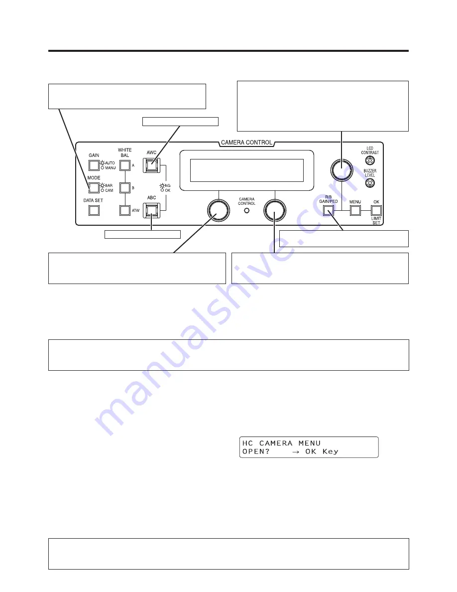
When the camera is to be controlled from the AW-RP655 controller

In the case of the AK-HC1800N camera, the 

following buttons on the AW-RP655 will not 

work.

• WHITE BAL A/B/ATW

• GAIN AUTO/MANU        • DATA SET

Each time the MODE button is pressed, the 

setting is switched between CAM and BAR.

The MODE button lights up at the BAR setting.

When the LCD is in the gain adjustment mode

   Select the desired gain setting from GAIN SELECT 

LOW to S.GAIN.

When the LCD is in the pedestal adjustment mode

  Adjust the M PEDESTAL setting (–150 to +150).

When the camera menu mode is established

  Perform the camera menu operations.

Switch between gain adjustment 

mode and pedestal adjustment mode.

For executing ABB.*

1

When the LCD panel is in the gain adjustment mode

  Adjust the B GAIN setting (–150 to +150).

When the LCD panel is in the pedestal adjustment mode

  Adjust the B PEDESTAL setting (–100 to +100).

*1:  The lamp of the ABB or AWB switch flashes while 

automatic white balance or automatic black balance 

is being executed, respectively. When ABB or AWB is 

completed successfully, the corresponding lamp goes 

off; when it is not completed successfully, it lights up.

For executing AWB.*

1

When the LCD panel is in the gain adjustment mode

  Adjust the R GAIN setting (–150 to +150).

When the LCD panel is in the pedestal adjustment mode

  Adjust the R PEDESTAL setting (–100 to +100).

When the AK-HC1800N, to which the motor drive lens is connected, has been directly 

connected to the AW-RP655 controller, zooming and focusing can be controlled using the 

controller’s joystick.

  When changing the panel display for use with the AK-HC1800N, please use panel sheet VGKB0007 (sold 

separately as a replacement part).

Procedure for camera menu operation (AW-RP655)

 Press the MENU button to set the LCD panel display to the menu mode.

 Turn the jog dial (main) to select CAMERA SETTING.

 Press the OK button.

  The right display appears on the LCD panel:  


When the OK button is pressed again, the menu of the AK-HC1800N appears on the 

monitor.

5

  Turn the jog dial (main) to modify menu items of the AK-HC1800N and change the 

data. When changing the data, the data settings are decremented by turning the dial 

clockwise and incremented by turning it counterclockwise. Push the jog dial (main) down 

to enter the settings.

6

 To exit the camera menu, press the MENU button or R/B GAIN/PED button.

Ver.0010 or a subsequent version of the AW-RP655 software must be installed in order for the 

AK-HC1800N to be controlled using the AW-RP655.

To check the software version of your AW-RP655, contact your dealer.

How to set up the system

Summary of Contents for AK-HC1800

Page 1: ...Operating Instructions Multi Purpose Camera Model No AK HC1800N Before operating this product please read the instructions carefully and save this manual for future use VQTB0328 ...

Page 2: ......

Page 3: ...NTERFERENCE USE THE RECOMMENDED ACCESSORIES ONLY WARNING TO REDUCE THE RISK OF FIRE OR ELECTRIC SHOCK DO NOT EXPOSE THIS APPARATUS TO RAIN OR MOISTURE THE APPARATUS SHALL NOT BE EXPOSED TO DRIPPING OR SPLASHING AND THAT NO OBJECTS FILLED WITH LIQUIDS SUCH AS VASES SHALL BE PLACED ON THE APPARATUS ...

Page 4: ...s convenience receptacles and the point where they exit from the apparatus 11 Only use attachments accessories specified by the manufacturer 12 Use only with the cart stand tripod bracket or table specified by the manufacturer or sold with the apparatus When a cart is used use caution when moving the cart apparatus combination to avoid injury from tip over 13 Unplug this apparatus during lightning...

Page 5: ...the camera is to be controlled from the AW RP655 controller 19 When the camera is to be controlled from the AW RP555 controller 20 Cable wiring specifications when connecting the camera directly to the AW CB400 AW RP655 or AW RP555 21 Operation procedure 22 How to adjust 23 Flange back adjustment for zoom lens 23 Lens iris gain volume adjustment 23 White balance adjustment 24 Color temperature and...

Page 6: ...AK HHD1500G and AK HDC1500G Note Characteristics New 2 3 2 2 million pixel CCD is employed 1920 H 1080 V 2 2 million pixel CCD is 2 3 in size being compact and light weight 14 bit A D conversion and brand new DSP featured Wide dynamic range achieved Crystal clear shooting even of images with different brightness levels Boosting of gain to a maximum 72 dB enabled Electronic extender function provid...

Page 7: ...ation Internal heat buildup can cause a fire Refer any servicing to qualified service personnel Handle the camera with care Protect the precision made lens by placing the lens cap over when the camera is not in use If the lens is not installed protect the surface of the prism by placing the body cap into the lens mount hole Use a mild blower or lens cleaning tissue designed for coated lenses to cl...

Page 8: ... Major operating controls and their functions Front view Top view Bottom view Rear view ...

Page 9: ... menu is on the screen When the menu is not displayed or the camera is in shooting mode the automatic white balance control AWB can be set with this switch UP ABB switch UP ABB The item just above can be selected by pressing this switch while the main menu is displayed While the Sub menu is displayed any setting can be brought up to a higher value with this switch When the menu is not displayed or...

Page 10: ...al heating or fire The life of this fan is approximately 30 000 hours at room temp 77 F 25 C Replace the fan as needed When the room temperature is higher than 95 F 35 C replace the fan 30 earlier Be sure to ask the dealer for the replacement Interface connector I F Pin No Signal 1 Gen lock signal GND 2 Not used 3 Not used 4 TX_N EIA422 TXD EIA232 output 5 RX_N EIA422 RXD EIA232 input 6 DC power s...

Page 11: ...th a performance equivalent or superior to the specifications given below AK HC1800N High density D sub 15 pin connector G L GND GND DC power supply input 12 V Not used Not used G L signal input Not used GND DC GND TX_N EIA422 TXD EIA232C output GND TX_P EIA422 output RX_N EIA422 RXD EIA232C input GND RX_P EIA422 input DC GND DC power supply input 12 V G L GND G L signal input GND RX_N EIA422 RXD ...

Page 12: ...sition information 5 Iris control 11 Focus position information 6 UNREG 12 V 12 NC Zoom Focus connector ZOOM FOCUS Used to connect the zoom focus control cables of lens Pin No Signal Pin No Signal 1 Focus control selection 7 COM 2 Zoom control selection 8 Focus control 3 GND 9 Zoom control 4 Forcible iris closing 10 Iris control selection 5 Iris control 11 COM Voltage 6 Voltage 12 COM Voltage Opti...

Page 13: ...tion Attach the provided filter to the iris control cable and zoom focus control cable Zoom focus control cable to ZOOM FOCUS connector When a pan tilt head is used connect the cable to the pan tilt head Iris control cable to IRIS connector Lens fixing ring knob Filter How to install on the camera housing pan tilt head tripod etc Precisely set the camera on the camera housing pan tilt head tripod ...

Page 14: ...a controller AK HRP150G AC adapter AW PS510AN Monitor HD SDI OUT IRIS AK HC1800N Select 1 as the PROTOCOL setting Before connecting the cables be sure to set the power switch of AC adapter to OFF Connect the multi cable to the interface connector of the camera and the opposite side to camera controller Set the AC adapter power switch to ON then the camera can be controlled After shooting set the A...

Page 15: ... AC adapter AW PS510AN ZOOM FOCUS Indoor pan tilt head AW PH400 Pan tilt control panel AW RP400 Camera controller AK HRP150G HD SDI AC adapter AW PS510AN Cable kit AW CAK4H1G Camera control 10BASE T straight cable Pan tilt control AK HC1800N Select 1 as the PROTOCOL setting How to set up the system ...

Page 16: ...W CB400 select 3 as the PROTOCOL setting HD SDI 10BASE T straight cable Pan tilt camera control Motor drive lens Monitor IRIS AC adapter AW PS510AN ZOOM FOCUS Indoor pan tilt head AW PH400 Pan tilt control panel AW RP400 Remote operation panel AW CB400 Camera connecting cable AW CA15H29G Monitor AC adapter AW PS510AN HD SDI HD SDI Motor drive lens AK HC1800N When mounting the camera on the pan til...

Page 17: ...ation To be locally purchased Controller AW RP655 or AW RP555 Monitor POWER SDI OUT RJ 45 relay adapter 10BASE T UTP category 5 straight cable MULTI AC adapter AW PS510AN G L input Outdoor pan tilt head AW PH650 Monitor AK HC1800N When mounting the camera on the pan tilt head Select 4 as the PROTOCOL setting Select DSUB as the GEN LOCK INPUT setting AK HC1800N When connecting this unit directly to...

Page 18: ...P D DOWN ZOOM TELE WIDE control FOCUS NEAR FAR control ND FILTER control DIGITAL EXTENDER control For capturing the camera statuses and synchronizing the data Statuses of panel switches only For setting DTL to either ON or OFF For selecting GAIN L M H or S1 S2 and S3 cannot be set For switching between CAM or BAR For controlling the MASTER PEDESTAL 150 to 150 For controlling IRIS AUTO MANU and LOC...

Page 19: ...in the gain adjustment mode Adjust the R GAIN setting 150 to 150 When the LCD panel is in the pedestal adjustment mode Adjust the R PEDESTAL setting 100 to 100 When the AK HC1800N to which the motor drive lens is connected has been directly connected to the AW RP655 controller zooming and focusing can be controlled using the controller s joystick When changing the panel display for use with the AK...

Page 20: ...ESET3 SYNCHRO PRESET8 1 500 PRESET4 PRESET9 1 1000 PRESET5 OFF PRESET10 Each time the MODE button is pressed the setting is switched between CAM and BAR The MODE button lights up at the BAR setting Use these buttons to perform the camera menu operations MENU This operates in the same way as MENU on the camera ITEM This operates in the same way as ENTER on the camera YES This operates in the same w...

Page 21: ...ring specifications when connecting the camera directly to the AW CB400 AW RP655 or AW RP555 Modular connector 8 pin plug High density D Sub 15 pin connector male AW CB400 AW RP655 AW RP555 How to set up the system ...

Page 22: ...g time The adjustment is necessary when the lighting condition or brightness is changed After adjusting the white balance once re adjustment is not needed under the same condition 5 Adjust the black balance This adjustment is needed when the camera is used for the first time or after leaving unused for a long time The adjustment is necessary when the ambient temperature is greatly changed or at th...

Page 23: ...cus ring and flange back adjust ring until the focus is adjusted within the zooming range After finishing the adjustment tighten the flange back fixing knob Flange back adjust ring Focus ring Flange back fixing knob Lens iris gain volume adjustment Iris gain adjust hole G or S is provided at front of the lens housing Adjust the iris according to the following procedure by using a screwdriver Set t...

Page 24: ...ference of shooting an indoor object from shooting one outdoors Studios are usually lighted with incandescent lamps and the color temperature of a white object in a studio is around 3 000K The color temperature of a white object outdoors is around 6 500K The former may look a little yellowish while the latter appears somewhat bluish when they are shot by a camera However the human eye does not rec...

Page 25: ...put by a two phenomenon oscilloscope and make the horizontal phase according to the camera menu Adjustment with GEN LOCK of SETTING menu When HD synchronizing signals are input Roughly adjust the synchronizing signal input and video signal output phases by H PHASE COARSE Finely adjust the synchronizing signal input and video signal output phases by H PHASE FINE When SD synchronizing signals are in...

Page 26: ...s adjustments whereas manual gain adjustments and manual CC filter settings were supported as color temperature adjustments However the problem with the user having to make these adjustments manually each time was that there was not enough time to select the optimum adjustments when a sudden emergency situation such as an earthquake arose with the result that shooting opportunities were lost Now u...

Page 27: ...VIDEO MENU only MANUAL functions OFF is the fixed setting with the FILM MENU The INTELLIGENT menus are not displayed either The conditions established by the intelligent functions may differ depending on the camera settings and optimal settings may not be selected even when filming under the same brightness and color temperature conditions When V MIX or FRAME MIX is switched to ON or OFF during an...

Page 28: ...P menu Use the UP DOWN switch to move the cursor to the target item and press the ENTER switch to move to a menu at a lower hierarchical level Using AK HRP150G camera controller Press the MENU ON OFF switch on the AK HRP150G so that its lamp lights The TOP menu now appears Move the cursor to the target item and press the MENU switch to move to a menu at a lower hierarchical level TOP menu When the...

Page 29: ... 29 MAINTENANCE menu 1 BLACK SHADING DETECTION For automatically correcting the black shading CORRECT DIG OFF ON For ON OFF control of the detection correction Setting of menu items ...

Page 30: ... 10 to 10 DRS ON For adjusting the gamma characteristics R GAMMA 15 to 15 DRS OFF 10 to 10 DRS ON For adjusting the gamma characteristics of the red in relation to the master gamma characteristics B GAMMA 15 to 15 DRS OFF 10 to 10 DRS ON For adjusting the gamma characteristics of the blue in relation to the master gamma characteristics M BLACK GAMMA 32 to 32 For adjusting the gamma characteristics...

Page 31: ...ck gamma correction ON or OFF When ON has been selected as the DRS setting the BLACK GAMMA setting does not take effect EFFECT DEPTH 1 to 5 For selecting the effects of the contrast adjustment when ON has been set for DRS DRS OFF ON For adjusting the contrast automatically when this is set to ON CINE GAMMA SELECT VIDEO REC FILM REC For selecting either the film use or video use cine gamma characte...

Page 32: ... 32 MAINTENANCE menu 3 FLARE R FLARE 000 to 100 G FLARE 000 to 100 B FLARE 000 to 100 For adjusting the flare correction FLARE OFF ON For turning the flare correction ON or OFF Setting of menu items ...

Page 33: ...e slope of the red in relation to the master knee slope B KNEE SLOPE 99 to 99 For adjusting the knee slope of the blue in relation to the master knee slope The M KNEE POINT and M KNEE SLOPE settings do not take effect when a setting other than MANUAL is selected for KNEE or ON is selected as the DRS setting when the VIDEO MENU has been selected or when FILM REC is selected as the CINE GAMMA SEL se...

Page 34: ...been selected A KNEE LEVEL 100 to 109 For setting the maximum level of auto knee This setting does not take effect when a setting other than AUTO is selected for KNEE or ON is selected as the DRS setting when the VIDEO MENU has been selected or when the FILM MENU has been selected M WHITE CLIP LVL 090 to 109 For setting the white clip level R WHITE CLIP LVL 15 to 15 For correcting the amount of re...

Page 35: ...eas when it is set to ON This setting does not take effect when a setting other than MANUAL is selected for KNEE or ON is selected as the DRS setting when the VIDEO MENU has been selected or when the FILM MENU has been selected R GAIN 200 to 200 For adjusting the gain of the red B GAIN 200 to 200 For adjusting the gain of the blue ND FILTER CLEAR 1 4 1 16 1 64 For selecting the ND filter setting W...

Page 36: ... level CRISP 00 to 31 For setting the noise elimination level of the detail signals LEVEL DEPENDENT 00 to 15 For removing the detail in the dark areas PEAK FREQUENCY 00 to 31 For setting the H DTL peak frequency KNEE APERTURE OFF ON For turning the emphasizing of the outlines for the high brightness areas ON or OFF KNEE APE LEVEL 0 to 5 For adjusting the knee aperture level Setting of menu items ...

Page 37: ... the direction DETAIL 31 to 31 For adjusting the detail gain in the direction DETAIL CLIP 00 to 63 For minimizing the glare caused by adding too much detail as a result of a detail clip adjustment DETAIL SOURCE G R 2 G B 2 2G B R 4 3G B 4 R G For setting the ratio of the RGB signal components which create the detail Setting of menu items ...

Page 38: ...t Y MAX 000 to 255 For setting the upper limit of the brightness in the skin tone specification area Y MIN 000 to 255 For setting the lower limit of the brightness in the skin tone specification area I CENTER 000 to 255 For setting the phase of the I axis in the skin tone specification area I WIDTH 000 to 255 For setting the phase width of the I axis in the skin tone specification area Q WIDTH 000...

Page 39: ...NDOW NORM1 NORM2 CENTR For setting the auto iris light metering area NORM1 The light is metered on the entire screen except around the edges NORM2 The light is metered on the entire screen except at the top CENTR The light is metered only in the area at the screen center IRIS MODE LENS CAM For switching between the iris gain control on the lens LENS and the menu CAM to adjust the focusing speed of...

Page 40: ...r setting the gain increase The increase is set in increments of 3 dB PIX MIX OFF 6dB For setting the addition of horizontal pixels ON or OFF V MIX OFF 6dB For setting the addition of vertical pixels ON or OFF FRAME MIX OFF 06dB to 24dB For setting the gain increase based on accumulation in the CCD image sensor The increase is set in increments of 6 dB H DETAIL LEVEL 00 to 63 For setting the H DET...

Page 41: ...ENCY 00 to 31 For setting the H DTL peak frequency M GAMMA 0 35 to 0 75 DRS OFF 10 to 10 DRS ON For adjusting the gamma characteristics M PED OFFSET 200 to 200 For adjusting the amount of offset in the black level R PED OFFSET 200 to 200 For adjusting the amount of offset in the R pedestal B PED OFFSET 200 to 200 For adjusting the amount of offset in the B pedestal Setting of menu items ...

Page 42: ...ight reversed REVERSE2 Top bottom reversed REVERSE3 Top bottom and left right reversed MATRIX TABLE A B For selecting the table in which the matrix data is to be stored MATRIX R G 31 to 31 MATRIX R B 31 to 31 MATRIX G R 31 to 31 MATRIX G B 31 to 31 MATRIX B R 31 to 31 MATRIX B G 31 to 31 For adjusting the color tone of each color phase Setting of menu items ...

Page 43: ...HASE 63 to 63 Cy SAT PHASE 63 to 63 G SAT PHASE 63 to 63 Yl SAT PHASE 63 to 63 R Mg SAT PHASE 63 to 63 Mg B SAT PHASE 63 to 63 B Cy SAT PHASE 63 to 63 Cy G SAT PHASE 63 to 63 G Yl SAT PHASE 63 to 63 Yl R SAT PHASE 63 to 63 For adjusting the color tone of each color phase Setting of menu items ...

Page 44: ...TUNGSTEN The color temperature is corrected electrically to attain white balance in 3200K degree environments GAIN SELECT LOW MID HIGH S GAIN1 to 3 For selecting LOW MID HIGH S GAIN1 S GAIN2 or S GAIN3 as the gain setting CAM ID OFF BAR ON For selecting how the camera ID is to be displayed OFF The camera ID is not displayed BAR The camera ID is displayed only in the color bar mode ON The camera ID...

Page 45: ...TRIX TABLE OFF A B For selecting OFF A or B as the matrix setting COLOR CORRECTION OFF ON For turning the color correction function ON or OFF DIGITAL EXTENDER OFF X2 For digitally doubling the images when set to X2 BAR SEL FULL 16 9 FULL 4 3 SMPTE 16 9 SMPTE 4 3 ARIB For selecting the color bars Select the 4 3 color bars for down conversion at the system side The color bars and characters will the...

Page 46: ... being executed AWB OK When the automatic white balance has been adjusted satisfactorily OUT RANGE RB When the automatic white balance has not been adjusted satisfactorily RB denotes the colors which were not balanced properly HIGH LIGHT NG When the lighting is too high LOW LIGHT NG When the lighting is too low ABB ACTIVE While automatic black balance is being executed IRIS CONTROL NG When the len...

Page 47: ... displayed with the color bars Switching from ON to OFF or vice versa is not possible when color bars have been set MENU SEL VIDEO MENU FILM MENU For selecting the menu display FAN OFF AUTO ON For selecting the operation mode of the air cooled fan OFF The fan is always off AUTO The fan is automatically controlled by the temperature sensor ON The fan is running at all times At the FAN OFF setting e...

Page 48: ...SYNCHRO For setting the shutter speed which was set by SYNCHRO SCAN SHUTTER SPEED 1 100 1 120 1 250 1 500 1 1000 1 2000 VIDEO MENU 180 0 deg 172 8 deg 144 0 deg 120 0 deg 90 0 deg 45 0 deg FILM MENU For setting the shutter speed at the SHUTTER ON setting SYNCHRO SCAN 60 32 Hz to 149 2 Hz 356 4 deg to 144 0 deg FILM MENU For setting the shutter speed in the synchro scanning mode Setting of menu ite...

Page 49: ...0 For roughly adjusting the horizontal phase H PHASE FINE 045 to 045 For finely adjusting the horizontal phase SD HD PHASE CRS 4 to 4 For roughly adjusting the phase of the HD video signals when SD sync signals have been input SD HD PHASE FINE 99 to 99 For finely adjusting the phase of the HD video signals when SD sync signals have been input Setting of menu items ...

Page 50: ... be used at a baud rate of 9600 bps 2 Information camera communication protocol EIA232 For connecting a PC This setting cannot be used at a baud rate of 9600 bps 3 Convertible PC control protocol EIA422 For connecting the AW CB400 baud rate fixed at 9600 bps 4 Convertible PC control protocol EIA232 For connecting the AW PH400 pan tilt head baud rate fixed at 9600 bps The protocol is actually switc...

Page 51: ...ally LOCK The status of the AGC and ATW adjustments is held as soon as the INTELLIGENT item setting is changed from AUTO to LOCK MANUAL Intelligent control is operated using the settings selected from the regular menus and camera controller When AUTO or LOCK is set on the INTELLIGENT1 menu INTELLIGENT2 is set to MANUAL Similarly when AUTO or LOCK is set on the INTELLIGENT2 menu INTELLIGENT1 is set...

Page 52: ...TO IRIS on the MAINTENANCE menu are not reflected The S GAIN settings gain detail gamma and pedestal settings on the MAINTENANCE menu are not reflected The ND FILTER setting for R B GAIN on the MAINTENANCE menu is not reflected ATW R B GAIN can be controlled from the menu and camera controller but the white balance is automatically adjusted if the subject is identified as being white AWB is execut...

Page 53: ...alance is adjusted automatically AGC ATW The above AGC and ATW adjustments are performed at the same time ND FILTER SELECT CLEAR 1 4 1 16 1 64 AUTO The ND filter setting during AGC operations is selected using this menu item AUTO Depending on the light quantity the ND filter is adjusted to the appropriate position CLEAR 1 4 1 16 1 64 The specified ND filter setting is fixed During AGC operations c...

Page 54: ...in is incremented straight from 0 dB to AGC MAX GAIN Conversely in the case of overexposure it is decremented straight from AGC MAX GAIN to 0 dB When MAX is selected set AGC MAX GAIN in such a way that the lens iris adjustment range is not exceeded If it is set so that this range is exceeded iris hunting may occur HI LIGHT DETECT 01 to 10 When the effective image is exposed to the light from a spo...

Page 55: ...filter and minus gain settings to adjust the range so that the appropriate level of exposure is achieved ATW AREA 25 50 90 The ATW white detection range is selected here The range is set to an area that is approximately 25 approximately 50 or approximately 90 of the horizontal and vertical angles of view from the screen center respectively ATW SPEED 1 to 5 The ATW convergence speed can be set to a...

Page 56: ... moving images The gain is incremented in the following sequence 18 dB for AGC 6 dB for PIX MIX 6 dB for V MIX SN This setting is for exercising control that gives priority to SN The gain is incremented in the following sequence 24 dB for FRAME MIX 6 dB for PIX MIX 6 dB for V MIX USER The gain is incremented in the sequence set using SUB MENU When the AGC MODE setting is changed intelligent contro...

Page 57: ...olution is reduced to half V MIX 00dB 06dB The extent of the vertical pixel addition is displayed here 00dB No vertical pixels are added 06dB The sensitivity is doubled over the 00 dB setting However the vertical resolution is reduced to half FRAME MIX 00dB 06dB 12dB 18dB 24dB The extent of the frame addition incrementing of gain by CCD storage is displayed here 00dB No frames are added 06dB to 24...

Page 58: ...elected as the control mode setting only a display appears Move the cursor to TYPE for each number set the gain type and then move the cursor to the numbers on the right and set the gain increment step Inside the parentheses on the right of the setting is the total gain The gain can be set in 3 dB increments for AGC up to a maximum of 36 dB in 6 dB increments for PMIX and VMIX and in 6 dB incremen...

Page 59: ... 59 2 SETTING menu 6 INTELLIGENT2 This menu is configured in the same way as the INTELLIGENT1 menu Setting of menu items ...

Page 60: ...s the operation mode When the setting of this item is changed the settings for the INTELLIGENT items on the INTELLIGENT1 and INTELLIGENT2 menus are also changed in tandem OFF MANUAL is set for INTELLIGENT1 and INTELLIGENT2 INTEL1 AUTO is set for INTELLIGENT1 and MANUAL for INTELLIGENT2 INTEL2 MANUAL is set for INTELLIGENT1 and AUTO for INTELLIGENT2 Setting of menu items ...

Page 61: ...0K Approx 4500K to 7000K 2 Approx 2500K to 5000K Approx 4000K to 8000K 3 Approx 2400K to 8000K Approx 2500K to 9500K 4 Approx 1900K to 10000K Approx 2400K to 10500K 5 Approx 1600K to 11000K Approx 1600K to 11000K IRIS ON LOCK LOCK MANUAL PANEL The IRIS operation status when the intelligent functions are locked is selected here LOCK The iris is held in the lock start status MANUAL The iris is switc...

Page 62: ...the CAM ID mode but displayed only when color bar signals are output in the BAR mode The status for setting the ID is established by moving the cursor above the colon and selecting it Move the cursor to the positions of the characters to be set select the characters and enter them Characters which can be entered Spaces upper case letters A to Z numbers 0 to 9 and symbols Setting of menu items ...

Page 63: ...ESET USER1 or USER2 can be selected as the LOAD destination when LOAD has been selected USER1 or USER2 can be selected as the STORE destination when STORE has been selected EXECUTE When EXECUTE is selected the LOAD OK or STORE OK message is displayed LOAD or STORE is executed when NO is switched to YES and the ENTER operation is performed COMPLETE is displayed after the data has been loaded or sto...

Page 64: ...E GAMMA SELECT BLACK STR LEVEL DYNAMIC LEVEL 3 FLARE R FLARE G FLARE B FLARE FLARE 4 KNEE WHITE CLIP M KNEE POINT R KNEE POINT B KNEE POINT M KNEE SLOPE R KNEE SLOPE B KNEE SLOPE A KNEE POINT A KNEE LEVEL M WHITE CLIP LVL R WHITE CLIP LVL B WHITE CLIP LVL KNEE WHITE CLIP HIGH COLOR 5 R B GAIN R GAIN B GAIN ND FILTER 6 DETAIL DETAIL TOTAL DTL LEVEL H DTL LEVEL CRISP LEVEL DEPENDENT PEAK FREQUENCY K...

Page 65: ...HASE 8 GAIN AUTO IRIS LOW GAIN MID GAIN HIGH GAIN A IRIS LEVEL A IRIS PEAK AVE A IRIS WINDOW IRIS MODE IRIS GAIN 9 S GAIN MODE TOTAL GAIN GAIN PIX MIX V MIX FRAME MIX H DETAIL LEVEL CRISP LEVEL DEPENDENT PEAK FREQUENCY M GAMMA M PED OFFSET R PED OFFSET B PED OFFSET 10 FRAME MODE SCAN REVERSE 11 MATRIX MATRIX TABLE MATRIX R G MATRIX R B MATRIX G R MATRIX G B MATRIX B R MATRIX B G Setting of menu it...

Page 66: ... SAT PHASE B_Cy SAT PHASE Cy_G SAT PHASE G_Yl SAT PHASE Yl_R SAT PHASE SETTING 1 MODE D5600K LIGHTING GAIN SELECT CAM ID CAM ID POSI MATRIX TABLE COLOR CORRECTION DIGITAL EXTENDER BAR SEL FORMAT STATUS MENU ON BAR MENU SEL FAN 2 SHUTTER SHUTTER MODE SHUTTER SPEED SYNCHRO SCAN 3 GEN LOCK GEN LOCK INPUT H PHASE COARSE H PHASE FINE SD HD PHASE CRS SD HD PHASE FINE 4 PROTOCOL PROTOCOL ...

Page 67: ...TW AREA ATW SPEED D5600K AGC MODE AGC MAX GAIN PIX MIX V MIX FRAME MIX SUB MENU 7 INTELLIGENT SET INTELLIGENT ATW WIDTH IRIS ON LOCK CAMERA ID ID When a scene file is loaded there may be inconsistencies in some of the items between the status of the connected controller and the status of the camera When the controller is operated in this status the status of the controller will be reflected ...

Page 68: ... 68 Appearance 3 9 16 90 6 5 16 160 15 32 12 17 32 13 2 4 5 8 117 Unit inch mm 1 3 4 44 5 ...

Page 69: ...temperature 32 F to 104 F 0 C to 40 C Storage temperature 4 F to 140 F 20 C to 60 C Weight Approx 3 3 lbs 1 5 kg Dimensions W H D 3 9 16 4 5 8 6 5 16 90 117 160 mm excluding protrusions Input output signal Video output HD SDI BNC 1 system SYNC input SYNC input GL input 3 value SYNC BB Camera connector D SUB 15 pin connector seat JAE D02 M15SAG 20L9E Control system Synchronous EIA 422 Lens connecto...

Page 70: ...FORMATION ORDERING 9 00 a m 5 00 p m PST 800 334 4881 24 Hr Fax 800 334 4880 Emergency after hour parts orders 800 334 4881 TECHNICAL SUPPORT Emergency 24 Hour Service 800 222 0741 Panasonic Canada Inc 5770 Ambler Drive Mississauga Ontario L4W 2T3 905 624 5010 Panasonic de Mexico S A de C V Av angel Urraza Num 1209 Col de Valle 03100 Mexico D F 52 1 951 2127 Panasonic Puerto Rico Inc San Gabriel I...

Reviews: