background image

– 30 –

Basic operations

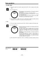
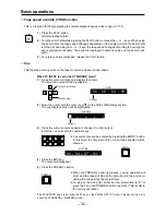
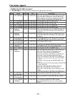
Shuttle (SHTL)

(1) The unit is placed in the shuttle mode when the SHTL button is pressed and the lamp

lights.

(2) Turn the search dial.

The tape speed changes depending on the angle by which the
dial is turned.

The tape speed is displayed on the search indicator.

The tape speed can be varied up to a maximum of 

n

50 times

the normal tape speed.

The maximum speed can be set by pressing the F6 (SHTL
MAX SP) key on the PANEL SET UP menu.

(3) When the STOP, FF, REW, PLAY, JOG, or VAR button is pressed, operation is directly

transferred to the mode that corresponds to the respective button.

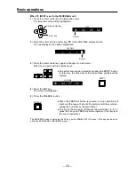
Jog

(1) The unit is placed in the JOG mode when the JOG button is pressed and the lamp lights.

(2) Turn the search dial.

When the dial rotation is stopped, the unit is placed in the still-
picture (STILL) mode.

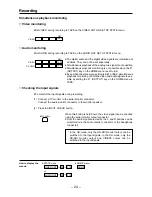
The tape protection mode is established after the still-picture
holding time has elapsed. (This time can be set using the F12
(STILL) key on the HOME SET UP menu and the ADJUST
control.)

The tape speed changes depending on the speed by which the
dial is turned.

The tape speed ranges from 

j

2 times to 

i

2 times of the nor-

mal tape speed. In the range from 

j

1 to 

i

2 times of the nor-

mal tape speed, the audio signals for all channels are output
from the AUDIO OUT connectors.

(3) When the STOP, FF, REW, PLAY, SHTL, or VAR button is pressed, operation is directly

How to display the

HOME SET UP menu:

PANEL SET UP menu:

menus:

#

#

F11

SET UP

F8

HOME

SHTL

JOG

Summary of Contents for AJ-HD3700B

Page 1: ...ti Format Digital HD Video Cassette Recorder Operating Instructions Hardware P E AJ Model No Before operating this product please read the instructions carefully and save this manual for future use VQT0F74 ...

Page 2: ...e operation the three pin plug must be inserted only into a standard three pin power outlet socket which is effectively grounded through normal household wiring Extension cords used with the equipment must be three core and be correctly wired to provide connection to the ground Incorrectly wired ex tension cords can be extremely hazardous The fact that the equipment operates satis factorily does n...

Page 3: ...5 of the FCC Rules To assure continued compliance follow the attached installation instructions and do not make any unauthorized modifications This equipment has been tested and found to comply with the limits for a Class A digital de vice pursuant to Part 15 of the FCC Rules These limits are designed to provide reason able protection against harmful interference when the equipment is operated in ...

Page 4: ...DISPOSED OF SAFELY THERE IS A DANGER OF SEVERE ELECTRICAL SHOCK IF THE CUT OFF PLUG IS INSERTED INTO ANY 13 AMP SOCKET If a new plug is to be fitted please observe the wiring code as shown below If in any doubt please consult a qualified electrician WARNING THIS APPLIANCE MUST BE EARTHED IMPORTANT The wires in this mains lead are coloured in accordance with the following code Green and Yellow Eart...

Page 5: ...ions for 2 units 19 Connection with an editing controller 20 Tapes 21 Recording 22 Playback 28 Basic operations 29 Manual Editing 35 Manual audio cross editing 37 Automatic insert assemble editing 38 Audio split editing 40 Variable memory Function 42 Connector signals 44 Video head cleaning 49 Rack mounting 50 Troubleshooting 51 Dip switch 52 Specifications 53 ...

Page 6: ...around 300 Mbps the result is a consistently high picture quality all the way through from the initial recording to editing Compact size light weight and low power consumption The unit is compact height equivalent to 5U depth at 201 2q lightweight 69 96 lbs low in power consump tion 260 W and easy to handle High cost performance In addition to featuring the basic functions and performance of HDD5 ...

Page 7: ...4i 720 59 94p and 480 59 94i formats Remote control In addition to the standard 9 pin serial RS 422A connector 50P parallel and RS 232C connectors are pro vided on the unit for remote control An AV control connector is also featured Slow motion search and editing functions Slow motion jog The incorporation of Panasonic s unique AT auto tracking mechanism makes slow motion playback and jogging poss...

Page 8: ...hannel signals is to be output to L R Each time the L or R button is pressed the selected output L or R signal changes in the sequence of CH1 CH2 CH3 CH4 CH5 CH6 CH7 CH8 and CUE When a 4 channel digital audio format is used either no sound is output or the sound of channels 1 through 4 is copied as the sound and output for the channels in the parentheses The channel now selected can be monitored b...

Page 9: ...lay lamps These lamps light in response to the number of errors channel condition 1 Lights during normal operation when the error value is minimal 2 Lights when the number of inner errors has increased 3 Lights when the number of video outer errors has increased 4 Lights when the number of audio outer errors has increased 17 SERVO lamp This lights when the servo is locked EJECT SD HD CHANNEL CONDI...

Page 10: ...his is the switch for switching between operation from the front panel of the unit and operation from the remote control terminals RS 422A RS 232C at the rear connector panel When REMOTE lamp lit is selected the recorder can be controlled via the remote control terminals at the rear connector panel When LOCAL lamp not lit is selected the recorder can be operated from the front panel 21 AUDIO LINE ...

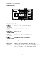
Page 11: ...EO IN F13 7 8 9 4 5 6 1 2 3 0 C T F F12 F11 F10 F9 F8 F7 F6 F5 F4 F3 F2 F1 L AUDIO MONITOR UNITY HEADPHONES PULL OPEN LEVEL CURSOR EXECUTE PREROLL ENTRY REW STOP REC EDIT PLAY REC INHIBIT STAND BY FF REVIEW PREVIEW R OUT IN OUT AUDIO LINE OUT SHTL JOG VAR INPUT CHECK REMOTE ADJUST POWER AUTO OFF ON OFF UNITY VAR TC CHR SET UP TEST DIAG FROM COPY BS ENT AUDIO PULL OPEN 32 33 34 35 30 31 29 28 24 25...

Page 12: ...3 ENTRY button EJECT SD HD CHANNEL CONDITION VIDEO AUDIO SERVO HOME ASSEM INSERT MULTI CUE VIDEO IN F13 7 8 9 4 5 6 1 2 3 0 C T F F12 F11 F10 F9 F8 F7 F6 F5 F4 F3 F2 F1 L AUDIO MONITOR UNITY HEADPHONES PULL OPEN LEVEL CURSOR EXECUTE PREROLL ENTRY REW STOP REC EDIT PLAY REC INHIBIT STAND BY FF REVIEW PREVIEW R OUT IN OUT AUDIO LINE OUT SHTL JOG VAR INPUT CHECK REMOTE ADJUST POWER AUTO OFF ON OFF UN...

Page 13: ...4 5 6 1 2 3 0 C T F F12 F11 F10 F9 F8 F7 F6 F5 F4 F3 F2 F1 L AUDIO MONITOR UNITY HEADPHONES PULL OPEN LEVEL CURSOR EXECUTE PREROLL ENTRY REW STOP REC EDIT PLAY REC INHIBIT STAND BY FF REVIEW PREVIEW R OUT IN OUT AUDIO LINE OUT SHTL JOG VAR INPUT CHECK REMOTE ADJUST POWER AUTO OFF ON OFF UNITY VAR TC CHR SET UP TEST DIAG FROM COPY BS ENT AUDIO PULL OPEN 44 45 46 47 48 49 50 Controls and their funct...

Page 14: ...nput of digital audio signals according to the AES standard CH5 6 CH7 8 1 connectors BNCt4 12 DIGITAL AUDIO OUT CH1 2 Output of digital audio signals according to the AES standard CH3 4 CH5 6 CH7 8 2 connectors BNCt4 1The items in brackets are not operative with 1080 59 94i audio 4 channels 720 59 94p audio 4 channels or 480 59 94i audio 4 channels format 2A function is provided to copy the sound ...

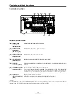
Page 15: ...1 When the normal black burst signal 59 94 Hz is input as the SD REF signal with the 1080 24p system asynchronization and a picture error will result 2This signal is not output with the 1080 24p system AC IN SIGNAL GND OUTPUT CH CH CH CH INPUT CH CH CH CH HD HD REMOTE IN ON OFF 1 2 3 SUPER SUPER IN IN OUT HD SDI SD SDI WFM VIDEO OUT REF IN REF OUT DIGITAL AUDIO 1 OUT1 OUT2 OUT 2 OUT 3 MONITOR MONI...

Page 16: ... connectors Digital audio signals CH1 CH2 CH3 CH4 CH5 CH6 CH7 CH8 and cue audio XLR 3Pt2 can be selected The items in brackets are not operative with 1080 59 94i audio 4 channels 720 59 94p audio 4 channels or 480 59 94i audio 4 channels format AC IN SIGNAL GND OUTPUT CH CH CH CH INPUT CH CH CH CH HD HD REMOTE IN ON OFF 1 2 3 SUPER SUPER IN IN OUT HD SDI SD SDI WFM VIDEO OUT REF IN REF OUT DIGITAL...

Page 17: ...ssible to switch between them using the menu 32 PARALLEL 50 pin parallel remote connector IN OUT terminal Mainly for connection of equipment produced by the user 50P ONoteN The AJ ER50 Video input and VIDEO PHASE functions are not operational as there is no correspondence with this recorder Also SYS PHASE should be set at this recorder and not at the AJ ER50 AC IN SIGNAL GND OUTPUT CH CH CH CH INP...

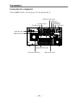
Page 18: ...THROUGH REMOTE OUT REMOTE IN OUT CONTROL PANEL V A CONTROL RS 232C PARALLEL IN OUT 50P SD SD SD ON OFF FUSE 125V 5A ACTIVE THROUGH CH 1 CH 2 CH 3 CH 4 CH 1 CH 2 CH 3 CH 4 CUE CUE L R OUT IN AUDIO OUT AUDIO IN MONITOR TIME CODE PUSH PUSH PUSH PUSH PUSH PUSH 75Ω 75Ω 3 4 π 1 2 π 7 8 π 5 6 π 7 8 π 5 6 π 3 4 π 1 2 π Waveform monitor output SD SDI input SD SDI output HD SDI input HD SDI output SD refere...

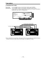
Page 19: ... IN OUTPUT CH CH CH CH INPUT CH CH CH CH HD HD REMOTE IN ON OFF 1 2 3 SUPER SUPER IN IN OUT HD SDI SD SDI WFM VIDEO OUT REF IN REF OUT DIGITAL AUDIO 1 OUT1 OUT2 OUT 2 OUT 3 MONITOR MONITOR SUPER SPARE ACTIVE THROUGH REMOTE OUT REMOTE IN OUT CONTROL PANEL V A CONTROL RS 232C PARALLEL IN OUT 50P SD SD SD ON OFF FUSE 125V 5A AUDIO OUT AUDIO IN MONITOR TIME CODE ACTIVE THROUGH PUSH PUSH PUSH PUSH PUSH...

Page 20: ... AUDIO PULL OPEN EJECT SD HD CHANNEL CONDITION VIDEO AUDIO SERVO HOME ASSEM INSERT MULTI CUE VIDEO IN F13 7 8 9 4 5 6 1 2 3 0 C T F F12 F11 F10 F9 F8 F7 F6 F5 F4 F3 F2 F1 L AUDIO MONITOR UNITY HEADPHONES PULL OPEN LEVEL CURSOR EXECUTE PREROLL ENTRY REW STOP REC EDIT PLAY REC INHIBIT STAND BY FF REVIEW PREVIEW R OUT IN OUT AUDIO LINE OUT SHTL JOG VAR INPUT CHECK REMOTE ADJUST POWER AUTO OFF ON OFF ...

Page 21: ...Use a screwdriver to push down the accidental erasure preven tion pins turn them 90 clockwise and then lift the screwdriver to set the pins at their down positions Pin A For inhibiting the recording of any signals Pin B For inhibiting the recording of video control signals Pin B is effective only when pin A is in the recording enabled position Pin C For identifying the 4 channel audio or 8 channel...

Page 22: ...nu Adjust the audio input signal level on the AUDIO IN menu Adjust the audio input signal levels for the digital audio channels CH1 to CH4 or CH1 CH8 when the 8 channel format has been selected and for analog cue Normally UNITY should be selected When adjusting the recording levels select the channel whose level is to be adjusted using the AUDIO IN menu for example to adjust the PCM CH1 level pres...

Page 23: ...ating mode Operation 1 Press the PLAY button while pressing the REC EDIT button Recording will start 2 Recording stops when the STOP button is pressed If the JOG SHTL or VAR button is pressed in place of the STOP button operation is di rectly transferred to the mode that corresponds to the respective button How to display the HOME menu TC CHR menu menus TC CHR HOME REC EDIT PLAY ...

Page 24: ...E2 simultaneous playback monitoring of both the video and audio signals is pos sible by setting the F1 OUTPUT key on the HOME menu to TAPE Checking the input signals To monitor the input signals during recording 1 Connect a TV monitor to the serial monitor connector Connect the audio monitor connector to the monitor speaker 2 Press the INPUT CHECK button While this button is held down the video si...

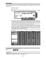
Page 25: ... the option of se lecting PsF or P for the VIDEO signal interface format When the format is selected using the cursor keys 3 4 and the ENT key is then pressed the format is entered In the same way the HD MAIN output and HD MONI output formats are selected using the cursor keys 3 4 and then entered by pressing the ENT key The table below lists the possible combinations of the output signals of the ...

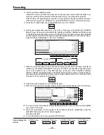
Page 26: ... AUDIO IN CUE INPUT menu to set it to D MIX and select the mixing channel with the F1 to F4 CUE MIX CH1 to CUE MIX CH4 keys In the case of the 1080 23 98 1080 24p 1080 25p 1080 50i and 576 50i formats or 1080 59 94i 8 channel audio version 720 59 94i 8 chan nel audio version and 480 59 94i 8 channel audio version formats select CH1 to CH4 and CH5 to CH8 with the F1 to 4 and the F10 to F13 keys 18 ...

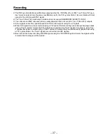
Page 27: ... P Non PsF outputs Other signals cannot be superimposed onto HD monitor outputs using True P signals When PsF signals have been recorded using a PsF system format and they are subsequently played back using a True P system format the PsF signals are converted into True P signals Conversely when True P signals have been recorded using a True P system format and they are subsequently played back usi...

Page 28: ... to CH4 or CH1 CH8 when the 8 channel format has been selected signal and the analog cue audio signal To adjust the audio signal level first press the F key all ocated to the channel concerned on the AUDIO OUT menu to highlight it and then adjust the level using the ADJUST control The adjustment range is from j to i12 dB for digital audio sig nals as well as for the analog cue signal To adjust all...

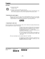
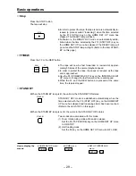
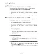
Page 29: ...ely 50 times of the normal playback speed In order to protect the tape the speed is reduced as the tape end is approached Use the F5 FF REW MAX SP key on the INTERFACE SET UP menu to change the fast forward or the rewind speed While the FF and the REW button are pressed at the same time the tape is stopped STAND BY When the STAND BY lamp is lit the unit is in the STAND BY ON status STAND BY OFF mo...

Page 30: ...laced in the JOG mode when the JOG button is pressed and the lamp lights 2 Turn the search dial When the dial rotation is stopped the unit is placed in the still picture STILL mode The tape protection mode is established after the still picture holding time has elapsed This time can be set using the F12 STILL key on the HOME SET UP menu and the ADJUST control The tape speed changes depending on th...

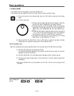
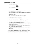
Page 31: ... are output from the AUDIO OUT connectors The maximum speed can be set by pressing the F12 VAR MAX SP key on the PANEL SET UP menu 3 When the STOP FF REW PLAY JOG or SHTL button is pressed operation is directly transferred to the mode that corresponds to the respective button Preset variable mode When the variable speed is preset playback starts at the set speed when the VAR button is pressed 1 Se...

Page 32: ...lighted 2 Move the cursor with the cursor key 4 to the CUE TIME display section The cue display section will be highlighted 3 Press the cursor center key again to change it to a bar cursor Enter the cue point with the number keys Cue points also can be entered by pressing the ENTRY button In this case the time data of the current tape position will be entered 4 Press the ENT key The cursor will di...

Page 33: ...current tape position will be entered 4 Press the ENT key The cursor will disappear 5 Press the PREROLL button When the PREROLL button is pressed cue up operation will start and the tape will stop at the preroll point the point pre ceding the cue point by the preroll time To stop at the cue point either set the preroll time to 0 or press the F key and PREROLL button together This results in the cu...

Page 34: ...cted 2 ENTER the new value with the number keys 3 Press the ENT key Cue points cannot be cleared When TC INPUT is set to the REVERSE mode Partial corrections cannot be made for cue points Repeat the input starting from step 1 when TC INPUT on page 33 was set to the REVERSE mode Cursor CUE TIME 00 H 41 M 07 S 04 F CUE TIME 00 H 44 M 07 S 04 F ...

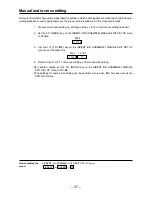
Page 35: ...the time code perform the time code related settings on the TC CHR menu 7 To enter the desired default value for the time code press the cursor center key at the HOME menu and set the desired value 8 Press the ASSEMBLE or the INSERT button to display the INSERT ASSEMBLE EDIT menu 9 Press the F12 key on the INSERT or the ASSEMBLE EDIT menu to set to MANUAL EDIT display the MANUAL EDIT menu and high...

Page 36: ...mode 13 Press the PREROLL button if preroll is required 14 Provide input of the editing source 15 Press the PLAY button to place the unit into playback mode 16 Press the REC EDIT button at the edit start IN point Editing will start 17 To end editing press the STOP or the REC EDIT button ...

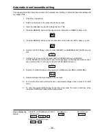
Page 37: ...y on the INSERT OR ASSEMBLE MANUAL EDIT SET UP menu to XFADE 3 Use the F12 FD TIME key on the INSERT OR ASSEMBLE MANUAL EDIT SET UP menu to set the fade time 4 Refer to steps 15 to 17 of manual editing and proceed with editing For audio V fading set the F13 MODE key on the INSERT OR ASSEMBLE MANUAL EDIT SET UP menu to VFADE The settings for audio cross editing can be performed only when EE1 has be...

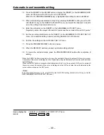
Page 38: ...1 P 2 key on the recorder s SET UP INTERFACE menu to MODE 1 Set the RS 422A control mode for each VTR depending on the player recorder connec tions Refer to the F1 P 2 key on the SET UP INTERFACE menu 8 Set the F13 REC INH key on the recorder s HOME menu to FREE or NRML REC 9 Select and adjust the input signals on the recorder 10 To record the time code perform the time code related settings on th...

Page 39: ...hannels 16 Perform the settings on the AUTO EDIT SET UP menu 17 Press the PREVIEW REVIEW button to preview 18 When the REC EDIT button is pressed automatic editing will start 19 To review the edited contents press the PREVIEW REVIEW button after completion of editing When the ENTRY button is pressed on its own the recorder s IN point is entered if there is no cursor Conversely if the cursor is dis...

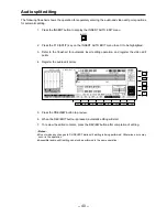
Page 40: ...atic insert editing operation and register the video edit points 4 Register the audio edit points 5 Press the PREVIEW button to preview 6 When the REC EDIT button is pressed automatic editing will start 7 To review the edited contents press the REVIEW button after completion of editing ONotesN Do not make any changes to CH SELECT while split editing is being performed Otherwise errors may occur in...

Page 41: ... AUTO EDIT menu 2 Press the F10 SPLIT key on the INSERT AUTO EDIT menu to set it to be highlighted 3 Use the automatic insert editing flowchart as a reference and register the VIDEO OUT point 4 Register the audio edit points 5 To preview the VIDEO OUT point 1 Use the cursor keys to move the cursor to the places where the VIDEO IN and OUT points were registered 2 Press the EXECUTE and the PREVIEW R...

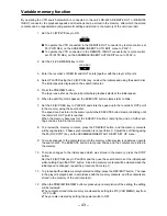
Page 42: ... When the edit IN point is passed the EXECUTE button s lamp starts to blink 7 Turn the search dial and store the tape speed in the memory The speed can be stored in the memory while the EXECUTE button s lamp is blinking When the memory becomes full the EXECUTE button s lamp lights and no further settings can be stored in the memory To make changes to the initial speed or memory contents repeat the...

Page 43: ...ory while the EXECUTE button s lamp is blinking until the recorder s OUT point is reached When the memory becomes full the EXECUTE button s lamp lights and no further set tings can be stored in the memory 8 To preview the memory contents press the PREVIEW button and the memory contents will be regenerated Phase synchronization is not performed Adjust the edit timing using the F9 DLY STRT key on th...

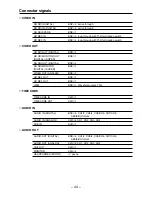
Page 44: ...TAL SUPER SD SDI OUT DIGITAL BNCk2 SD SDI MONITOR BNCk1 DIGITAL SUPER VIDEO OUT ANALOG BNCk3 HD REF OUT BNCk1 SD REF OUT BNCk1 WFM BNCk1 Waveform output 75 TIME CODE TIME CODE IN XLRk1 TIME CODE OUT XLRk1 AUDIO IN AUDIO IN DIGITAL BNCk4 CH1 2 CH3 4 CH5 CH6 CH7 CH8 AES EBU format AUDIO IN ANALOG XLRk4 CH1 CH2 CH3 CH4 CUE IN XLRk1 AUDIO OUT AUDIO OUT DIGITAL BNCk4 CH1 2 CH3 4 CH5 CH6 CH7 CH8 AES EBU...

Page 45: ...is in the loosing or STBY OFF mode it is set to the STNBY ON mode as soon as it receives this command When the VTR is in the loosing or STBY ON mode it is set to the STNBY OFF mode as soon as it receives this command This enables RS 422 control However the VTR must be in the REMOTE mode for this command to take effect This disables RS 422 control This enables the REMOTE OP MAP functions When the M...

Page 46: ... pins 24 and 34 Spare When this has become active the tape is prerolled from the cue up point on the VTR s menu When the VTR has opened the AUTO EDIT menu The tape is prerolled from the time for the IN point when the AUTO EDIT menu IN point has been entered The tape is prerolled from the time for the current position when the AUTO EDIT menu IN point has not been entered When the VTR has opened a m...

Page 47: ...ven if CTL has been detected during recording EDIT REC or PLAY while editing is being performed In the same way it will not become active even if CTL has been detected during normal recording when the home menu function REC INH setting has been set to FREE This becomes active when CASSETTE INH has been set to the all recording inhibit status This becomes active when the VTR has been placed in the ...

Page 48: ...V A CONTROL Pin No 1 2 3 4 5 6 7 Pin No 8 9 13 14 15 Signal FRAME GROUND REM G REM RX X REMOTE CONTROL PROTOCOL RECEIVE Signal REM TX X REMOTE CONTROL PROTOCOL TRANSMIT REM RX Y REMOTE CONTROL PROTOCOL RECEIVE REM TX Y REMOTE CONTROL PROTOCOL TRANSMIT CONTROL PANEL Pin No 1 2 3 4 5 6 7 8 9 10 Pin No 11 12 13 14 15 16 17 18 19 20 Signal Headphone L Clock i RECEIVE DATA i RECEIVE ENABLE i TRANSMIT D...

Page 49: ...e using the optional digital VTR dedicated head cleaning tape AJ TDCLS P to clean the heads be sure to read carefully the Precautions provided with the cleaning tape In addition to cleaning the video heads every day make it a rule once a week to clean the tape transport system and once a month to clean the reel bases and carriage cassette holder front guide angles For further details please consul...

Page 50: ...re to attach the inner members to the VTR using the screws for all of the four holes 2 Mount the outer member brackets onto the rack Check that the height of the brackets is the same at the left and right 3 Remove the two front screws on the VTR s two side panels 4 Mount the AJ MA37P rack mounting adapters using the four supplied M4 screws with spring washers 5 Mount the VTR in the rack After moun...

Page 51: ...elops proceed with the following 4 steps to take up the tape 3 Insert a screwdriver into hole A for an S or M cassette or hole A for an L cassette and press the manual lever of the take up reel The tape will be taken up by pressing this lever 4 Remove the tape from the cylinder by performing the operations in steps 2 and 3 When turning the loading motor keep turning it until the position is reache...

Page 52: ...tte is forcibly ejected automatically For test purposes For test purposes SW6071 1 2 3 4 6 7 8 ON Normal Ejected OFF Normal Prohibited Normal Not ejected Normal Normal SYSCON microcomputer DIP switch specifications History No 6 From SYSCON Ver 0 12 The underlining indicates the factory settings SERVO microcomputer DIP switch specifications SW2001 1 2 3 4 Purpose For AT adjustments For AT adjustmen...

Page 53: ...0i 480 59 94i Recording tracks Digital video audio 12 tracks field 1080 23 98p 1080 24p 1080 25p 1080 50i 1080 59 94i 720 59 94p 480 59 94i 16 tracks field 576 50i Cue track 1 track Time code track 1 track Control track 1 track Tape speed 185 995 mm sec 576 50i 167 228 mm sec 1080 59 94i 720 59 94p 480 59 94i 139 496 mm sec 1080 50i 1080 25p 133 782 mm sec 1080 23 98p 1080 24p Tapes used D5 casset...

Page 54: ...DI SMPTE 259M 272M ITU R BT 656 4 standards complied BNC k 2 active through HD reference input Analog tri level sync n0 3V loop through 75 ohms ON OFF switchable BNC k 2 SD reference input Analog composite loop through 75 ohms ON OFF switchable BNC k 2 Output connectors HD serial output 1 5 Gbps Superimposing possible for monitor OUT BNC k 4 SD serial output Component SDI output SMPTE 259M 272M 29...

Page 55: ...chable Cue track Frequency response 100 Hz to 12 kHz n3 0 dB Audio input connectors Analog input CH1 CH4 i4 0 j20 dBm dBu switchable with 600 load 600 high impedance switchable XLR k 4 Digital input AES3 format 75 ohms unbalanced BNC k 4 CH1 CH2 CH3 CH4 No operation for CH5 CH6 and CH7 CH8 in 480 59 94i 4CH CH5 CH6 CH7 CH8 1080 59i 4CH or 720 59p 4CH format Cue track input i4 0 j20 dBm dBu switcha...

Page 56: ... k 1 RS 422A input RS 422A interface D Sub 9P k 1 RS 422A output RS 422A interface D Sub 9P k 1 RS 422A input output RS 422A interface D Sub 9P k 1 RS 232C RS 232C interface D Sub 25P k 1 Parallel input output Parallel communication D Sub 50P k 1 V A control Video remote control D Sub 15P k 1 Control panel For connecting front control panel 20P k 1 Accessory supplied Power cord 1 Optional accessor...

Page 57: ... 57 ...
Page 58: ...9 00 a m 5 00 p m EST 800 334 4881 24 Hr Fax 800 334 4880 Emergency after hour parts orders 800 334 4881 TECHNICAL SUPPORT Emergency 24 Hour Service 800 222 0741 Panasonic Canada Inc 5770 Ambler Drive Mississauga Ontario L4W 2T3 905 624 5010 Panasonic de Mexico S A de C V Av angel Urraza Num 1209 Col de Valle 03100 Mexico D F 52 1 951 2127 Panasonic Sales Company Division of Matsushita Electric of...

Reviews: