EXPLODED VIEWS &
REPLACEMENT PARTS LIST
Model No. :
AG-AC7P
CONTENTS
S7-1. FRAME AND CASING SECTION (1) .................................................................................... MPL-1
S7-2. FRAME AND CASING SECTION (2) .................................................................................... MPL-3
S7-3. HANDLE SECTION ............................................................................................................... MPL-5
S7-4. COVER SECTION ................................................................................................................. MPL-7
S7-5. EVF SECTION....................................................................................................................... MPL-9
Note:
1.
*
Be sure to make your orders of replacement parts according to this list.
2. Unless otherwise specified, all resistors are in OHMS, K=1,000 OHMS,
all capacitors are in MICROFARADS (
F) P=
F.
3. The P.C.Board unit marked with “
■
” shown below the main assembled parts.
4. The parts marked with E on the exploded view show the electric parts.
5. INPORTANT
SAFETY
NOTICE
Components identified with the mark
!
have the special characteristics for safety When replacing any
of these components, use only the same type.
6. The marking (RTL) indicates the retention time is limited for this item.
After the discontinuation of this assembly in production, it will no longer be available.
7.
“M”
in Remark column indicates needed in the periodical maintenance.
S7-6. LCD SECTION....................................................................................................................... MPL-11
S7-7. PACKING PARTS AND ACCESSORIES SECTION............................................................. MPL-13
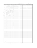
ELECTRICAL REPLACEMENT PARTS LIST ................................................................................ EPL-1
Summary of Contents for AG-AC7P
Page 3: ... 3 ...
Page 4: ... 4 ...
Page 5: ... 5 ...
Page 7: ... 7 ...
Page 8: ... 8 ...
Page 9: ... 9 ...
Page 10: ... 10 ...
Page 12: ...INF 1 1 Location of Controls and Components ...
Page 13: ...INF 2 ...
Page 14: ...INF 3 ...
Page 15: ...INF 4 ...
Page 16: ...INF 5 ...
Page 17: ...INF 6 Motion picture recording mode Still picture recording mode Playback mode ...
Page 30: ...DIS 7 Fig D10 1 3 8 Removal of the Lens Int P C B Unit and Main P C B Unit Fig D11 Fig D12 ...
Page 33: ...DIS 10 Fig D18 1 3 14 Removal of the Handle Zoom P C B Unit Fig D19 Fig D20 ...
Page 35: ...DIS 12 1 3 17 Removal o f the EVF Unit and EVF Int P C B Unit Fig D24 Fig D25 ...
Page 38: ...DIS 15 Fig D34 1 3 23 Removal of the LCD Unit and Moni tor P C B Unit Fig D35 ...
Page 39: ...DIS 16 Fig D36 1 3 24 Removal of the MOS Unit and IR Fil ter Fig D37 ...
Page 40: ...DIS 17 1 3 25 Removal of the Focus Motor Fig D38 1 3 26 Removal of the Zoom Motor Fig D39 ...
Page 139: ...03 1 S7 6 LCD Section B87 16 98 133 132 101 100 99 81 97 96 B86 B88 84 ...
Page 144: ...MHOR2280 01234567S ...


