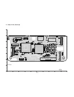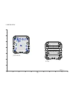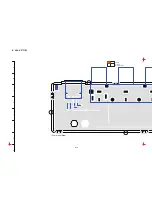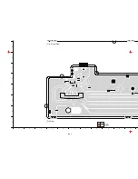
S-21
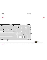
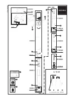
CL4501
CL4502
C4501
C4502
C4504
C4505
C4506
C4599
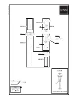
LB4501
LB4506
LB4507
LB4508
LB4509
LB4510
LB4511
MK1
MK2
MK3
MK4
R4502
R4506
R4599
VZ4501
VZ4502
16
15
14
13
12
11
10
9
8
7
6
5
4
3
2
1
FP4501
VZ4503
C4503
1
2
3
4
5
6
JK4501
8
7
6
5
4
3
2
1
JK4502
14
13
12
11
10
9
8
7
6
5
4
3
2
1
JK4503
LB4503
LB4504
LB4505
MK5
MK6
MK7
MK8
R4501
R4503
R4504
R4505
(Component Side)
2/4
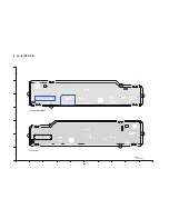
HDC-MDH1
Jack P.C.B.
(Foil Side)
4/4
(Component Side)
1/4
21
20
19
18
17
16
15
14
13
12
11
10
9
8
7
6
5
4
3
2
1
N
M
L
K
J
I
H
G
F
E
D
C
B
A
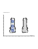
3/4
(Foil Side)
(Component Side)
HDC-MDH1
Jack P.C.B.
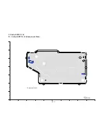
(Foil Side)
HDC-MDH1
Jack P.C.B.
$*$&
Jack P.C.B.
S-21
Summary of Contents for AG-AC7P
Page 3: ... 3 ...
Page 4: ... 4 ...
Page 5: ... 5 ...
Page 7: ... 7 ...
Page 8: ... 8 ...
Page 9: ... 9 ...
Page 10: ... 10 ...
Page 12: ...INF 1 1 Location of Controls and Components ...
Page 13: ...INF 2 ...
Page 14: ...INF 3 ...
Page 15: ...INF 4 ...
Page 16: ...INF 5 ...
Page 17: ...INF 6 Motion picture recording mode Still picture recording mode Playback mode ...
Page 30: ...DIS 7 Fig D10 1 3 8 Removal of the Lens Int P C B Unit and Main P C B Unit Fig D11 Fig D12 ...
Page 33: ...DIS 10 Fig D18 1 3 14 Removal of the Handle Zoom P C B Unit Fig D19 Fig D20 ...
Page 35: ...DIS 12 1 3 17 Removal o f the EVF Unit and EVF Int P C B Unit Fig D24 Fig D25 ...
Page 38: ...DIS 15 Fig D34 1 3 23 Removal of the LCD Unit and Moni tor P C B Unit Fig D35 ...
Page 39: ...DIS 16 Fig D36 1 3 24 Removal of the MOS Unit and IR Fil ter Fig D37 ...
Page 40: ...DIS 17 1 3 25 Removal of the Focus Motor Fig D38 1 3 26 Removal of the Zoom Motor Fig D39 ...
Page 139: ...03 1 S7 6 LCD Section B87 16 98 133 132 101 100 99 81 97 96 B86 B88 84 ...
Page 144: ...MHOR2280 01234567S ...


