25
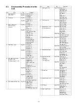
8.3.
Disassembly Procedure for the
Unit
No.
Item
Fig.
Removal
1
Lens Hood Unit,
Lens Mask
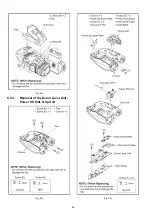
(Fig. D1) Lens Hood Unit
(Fig. D2) Screw (A) × 4
Lens Mask
2
Grip Ass’y
(Fig. D3) Screw (B) × 7
Screw (C) × 1
(Fig. D4) Locking tab × 2
Flex
Grip Ass’y
3
Zoom Lever Unit,
Power SS Unit,
Grip Unit
(Fig. D5) Screw (D) × 2
Screw (E) × 2
Flex
Convex × 2
(Fig. D6) Convex × 3
Power SS Earth Plate
Screw (F) × 2
Grip Zoom FFC
Power SS Unit
Grip Unit
Screw (G) × 2
Photo Shot Button
Photo Earth Plate
Zoom Lever Unit
Zoom Base
4
Side Case L Unit
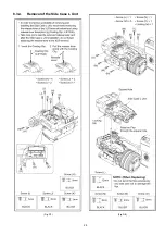
(Fig. D7) Screw (H) × 6
Screw (I) × 2
Screw (J) × 2
Screw (K) × 1
(Fig. D8) Screw (L) × 1
Screw (M) × 5
Screw (N) × 1
Screw (O) × 1
Locking tab × 1
Side Case L Unit
5
XLR Rear P.C.B. Unit,
AV Jack P.C.B.,
DC/Remote Jack P.C.B.
(Fig. D9) Screw (P) × 4
XLR Angle R
FP6022 (Flex)
P6502 (Connector)
Flex
Screw (Q) × 2
XLR Rear P.C.B. Unit
(Fig. D10) Jack FFC
M6 Nut × 1
Screw (R) × 4
Convex × 2
Jack Frame
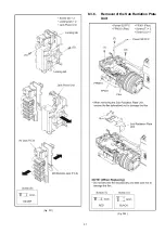
(Fig. D11) Screw (S) × 2
Locking tab × 2
Jack Piece Unit
AV Jack P.C.B.
DC/Remote Jack P.C.B.
6
Sub Radiation Plate Unit
(Fig. D12) Power SS FFC
FP6010 (Flex)
FP301 (Flex)
Screw (T) × 2
Screw (U) × 1
Sub Radiation Plate Unit
7
LED Light P.C.B.
(Fig. D13) Screw (V) × 1
Locking tab × 2
LED Light Cover
Screw (W) × 2
Mic Case A
Flex
Screw (X) × 1
LED Light Lens
LED Light P.C.B.
8
XLR Front Unit
(Fig. D14) Screw (Y) × 2
Screw (Z) × 2
Cable Clamper
FP6712 (Flex)
XLR Front Unit
9
Handle Case T Unit,
HA Top Angle Unit
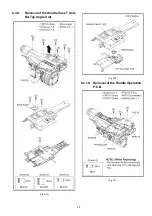
(Fig. D15) FP6716 (Flex)
Screw (a) × 6
Screw (b) × 3
Shoe Angle
Screw (c) × 1
(Fig. D16) REC Button
Handle Case T Unit
HA Top Angle Unit
10 Handle Operation P.C.B.
(Fig. D17) Screw (d) × 3
FP6710 (Flex)
FP6713 (Flex)
FP6708 (Flex)
P6710 (Connector)
Hooking part × 1
(Fig. D18) PS6719 (Connector)
FP6714 (Flex)
Handle Operation P.C.B.
11 Handle Slide Ass’y
(Fig. D19) Screw (e) × 2
LED Light Angle
Screw (f) × 3
Locking tab × 3
Handle Slide Ass’y
12 Handle Slide Unit,
LCD unit,
LCD Case T,
LCD Hinge Unit
(Fig. D20) Screw (g) × 4
Handle Slide Unit
Screw (h) × 2
Screw (i) × 2
(Fig. D21) Locking tab × 6
LCD Case T
Flex A
Flex B
LCD Hinge Unit
LCD Unit
13 Microphone
(Fig. D22) Locking tab × 2
Mic Case B
Mic Cushion A
Mic Cushion B
Mic Cushion C
Microphone
14 Handle Case L Unit
(Fig. D23) Screw (j) × 1
Screw (k) × 1
Screw (l) × 1
Locking tab × 3
Handle Case L Unit
15 ND Case
(Fig. D24) Screw (m) × 2
Locking tab × 2
ND Case
16 Side Case R Ass’y
(Fig. D25) Screw (n) × 6
Screw (o) × 1
Screw (p) × 2
FP6901 (Flex)
Side Case R Ass’y
No.
Item
Fig.
Removal
Summary of Contents for AG-AC30PJ
Page 4: ...3 Model No AG AC30PJ PB ...
Page 5: ...4 ...
Page 6: ...5 ...
Page 7: ...6 ...
Page 8: ...7 Model No AG AC30EJ ...
Page 9: ...8 ...
Page 12: ...11 ...
Page 14: ......
Page 16: ...13 ...
Page 17: ...14 ...
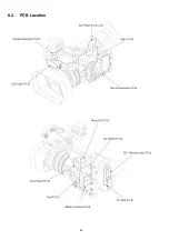
Page 37: ...24 8 2 PCB Location ...
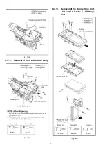
Page 41: ...28 Fig D4 8 3 3 Removal of the Zoom Lever Unit Power SS Unit Grip Unit Fig D5 Fig D6 ...
Page 42: ...29 8 3 4 Removal of the Side Case L Unit Fig D7 Fig D8 ...
Page 43: ...30 8 3 5 Removal of the XLR Rear P C B Unit AV Jack P C B DC Remote Jack P C B Fig D9 Fig D10 ...
Page 44: ...31 Fig D11 8 3 6 Removal of the Sub Radiation Plate Unit Fig D12 ...
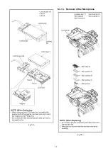
Page 45: ...32 8 3 7 Removal of the LED Light P C B Fig D13 8 3 8 Removal of the XLR Front Unit Fig D14 ...
Page 48: ...35 Fig D21 8 3 13 Removal of the Microphone Fig D22 ...
Page 49: ...36 8 3 14 Removal of the Handle Case L Unit Fig D23 8 3 15 Removal of the ND Case Fig D24 ...
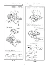
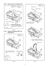
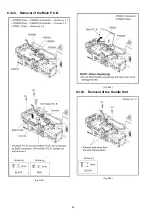
Page 53: ...40 8 3 22 Removal of the Main P C B Fig D32 Fig D33 8 3 23 Removal of the Handle Unit Fig D34 ...
Page 55: ...42 Fig D39 8 3 26 Removal of the Battery Catcher P C B Fig D40 ...
Page 56: ...43 8 3 27 Removal of the Speaker Fig D41 8 3 28 Removal of the EVF Unit Fig D42 ...
Page 57: ...44 Fig D43 ...
Page 60: ...49 Level Shot Adjutment Chart ...
Page 62: ...51 9 1 2 Adjustment Items Adjustment item as follows ...
Page 65: ...54 ...
Page 66: ...55 ...
Page 67: ...56 ...
Page 68: ...57 ...
Page 69: ...58 ...
Page 70: ...59 ...
Page 71: ...60 ...
Page 72: ...61 ...
Page 85: ......
Page 86: ......
Page 116: ......
Page 119: ...1 5 2 6 R L 6 5 5 1 R L 6 5 5 2 F P 6 5 5 1 D 6 5 5 1 D 6 5 5 2 M K 1 M K 2 ...
Page 120: ......
Page 122: ...MK1 MK2 C3901 D3901 C3902 D3902 ...
Page 125: ...M K 3 M K 4 D 6 5 0 1 D 6 5 0 2 D 6 5 0 3 D 6 5 0 4 D 6 5 0 5 D 6 5 0 6 D 6 5 0 7 D 6 5 0 8 ...
Page 126: ...8 7 2 5 1 CL6501 CL6502 CL6503 RL6504 RL6505 FP6501 MK1 MK2 ...
Page 127: ...1 5 2 6 4 1 M K 1 M K 2 R L 6 9 3 6 F P 6 9 3 6 F P 6 9 3 7 ...
Page 128: ...1 ET6931 RL6937 ...
Page 131: ...1 4 2 3 M K 3 M K 4 J K 6 3 0 1 ...

