


9
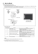
3.
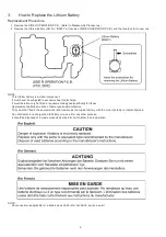
How to Replace the Lithium Battery
Replacement Procedure
1. Remove the SIDE R OPERATION P.C.B.. (Refer to Disassembly Procedures.)
2. Remove the Lithium battery (Ref. No. “B6901” at foil side of SIDE R OPERATION P.C.B.) and then replace it into new one.
NOTE:
This Lithium battery is a critical component.
It must never be subjected to excessive heat or discharge.
It must therefore only be fitted in requirement designed specifically for its use.
Replacement batteries must be of same type and manufacture.
They must be fitted in the same manner and location as the original battery, with the correct polarity contacts observed.
Do not attempt to re-charge the old battery or re-use it for any other purpose.
It should be disposed of in waste products destined for burial rather than incineration.
NOTE:
Above caution is applicable for a battery pack which is for
AG-AC30
series, as well.
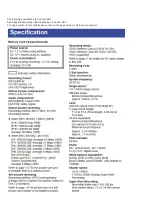
Summary of Contents for AG-AC30PJ
Page 4: ...3 Model No AG AC30PJ PB ...
Page 5: ...4 ...
Page 6: ...5 ...
Page 7: ...6 ...
Page 8: ...7 Model No AG AC30EJ ...
Page 9: ...8 ...
Page 12: ...11 ...
Page 14: ......
Page 16: ...13 ...
Page 17: ...14 ...
Page 37: ...24 8 2 PCB Location ...
Page 41: ...28 Fig D4 8 3 3 Removal of the Zoom Lever Unit Power SS Unit Grip Unit Fig D5 Fig D6 ...
Page 42: ...29 8 3 4 Removal of the Side Case L Unit Fig D7 Fig D8 ...
Page 43: ...30 8 3 5 Removal of the XLR Rear P C B Unit AV Jack P C B DC Remote Jack P C B Fig D9 Fig D10 ...
Page 44: ...31 Fig D11 8 3 6 Removal of the Sub Radiation Plate Unit Fig D12 ...
Page 45: ...32 8 3 7 Removal of the LED Light P C B Fig D13 8 3 8 Removal of the XLR Front Unit Fig D14 ...
Page 48: ...35 Fig D21 8 3 13 Removal of the Microphone Fig D22 ...
Page 49: ...36 8 3 14 Removal of the Handle Case L Unit Fig D23 8 3 15 Removal of the ND Case Fig D24 ...
Page 53: ...40 8 3 22 Removal of the Main P C B Fig D32 Fig D33 8 3 23 Removal of the Handle Unit Fig D34 ...
Page 55: ...42 Fig D39 8 3 26 Removal of the Battery Catcher P C B Fig D40 ...
Page 56: ...43 8 3 27 Removal of the Speaker Fig D41 8 3 28 Removal of the EVF Unit Fig D42 ...
Page 57: ...44 Fig D43 ...
Page 60: ...49 Level Shot Adjutment Chart ...
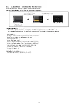
Page 62: ...51 9 1 2 Adjustment Items Adjustment item as follows ...
Page 65: ...54 ...
Page 66: ...55 ...
Page 67: ...56 ...
Page 68: ...57 ...
Page 69: ...58 ...
Page 70: ...59 ...
Page 71: ...60 ...
Page 72: ...61 ...
Page 85: ......
Page 86: ......
Page 116: ......
Page 119: ...1 5 2 6 R L 6 5 5 1 R L 6 5 5 2 F P 6 5 5 1 D 6 5 5 1 D 6 5 5 2 M K 1 M K 2 ...
Page 120: ......
Page 122: ...MK1 MK2 C3901 D3901 C3902 D3902 ...
Page 125: ...M K 3 M K 4 D 6 5 0 1 D 6 5 0 2 D 6 5 0 3 D 6 5 0 4 D 6 5 0 5 D 6 5 0 6 D 6 5 0 7 D 6 5 0 8 ...
Page 126: ...8 7 2 5 1 CL6501 CL6502 CL6503 RL6504 RL6505 FP6501 MK1 MK2 ...
Page 127: ...1 5 2 6 4 1 M K 1 M K 2 R L 6 9 3 6 F P 6 9 3 6 F P 6 9 3 7 ...
Page 128: ...1 ET6931 RL6937 ...
Page 131: ...1 4 2 3 M K 3 M K 4 J K 6 3 0 1 ...


