Panametrics C-ET Installation Manual Download Page 21

Model C-ET Installation Guide

13


1.3.2.2

Pipe Survey to Determine OD and Wall Thickness

Finding a location where the pipe is concentric is important for optimum accuracy and performance. If possible, 

perform a pipe survey with an ultrasonic thickness gauge to find the best location.
Measure the outside diameter (OD) of the pipe using a tape measure or other suitable device. Mark a circumferential 

line with the tape measure.

Note:

If you are using a PT878 thickness gauge at extreme high or low temperatures, it can be in contact with the 

pipe for less than two seconds only and then must be removed. Allow it to cool for a minimum of 2 minutes 

before taking another measurement.

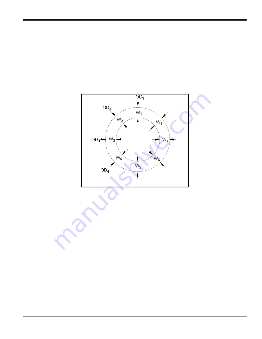
Now measure the OD and the wall thickness at eight points along the pipe circumference at 45° intervals (shown in 

Figure 8), three times per point, and record the mean values. Use the mean value for the wall thickness.

Figure 8: Measuring the Wall Thickness

To determine the meter's correction factor for non-concentric pipes, calculate the mean inside pipe diameter (ID) 

and the pipe ID at the transducer locations. Then divide the square of the mean ID by the square of the ID at the 

transducer location, as shown in the equations below, where ODX is the outside diameter at a given point, and WX is 

the wall thickness at a given point (as shown in Figure 3-6 on the previous page).
mean ID = [((OD

– (W

1

 + W

2

)) + (OD

2

 – (W

2

 +W

6

)) + (OD

3

 – (W

3

 + W

7

)) + (OD

4

 – (W

4

 + W

8

))] / 4

K

for non-concentric pipe

Mean ID

2

ID at transducer location

2

--------------------------------------------------

=

Summary of Contents for C-ET

Page 1: ...panametrics com Flow 916 083 B August 2021 Model C ET Ultrasonic Flow Transducer System Installation Guide...

Page 2: ......

Page 3: ...one or more registered trademarks of Baker Hughes Company and its subsidiaries in one or more countries All third party product and company names are trademarks of their respective holders Model C ET...

Page 4: ...ii no content intended for this page...

Page 5: ...ers 9 1 3 2 2 Pipe Survey to Determine OD and Wall Thickness 13 1 3 2 3 Fluid Soundspeed 14 1 3 3 Installing the V Clamping Fixtures and Transducers 14 1 3 3 1 Tools and Equipment Needed 14 1 3 3 2 Se...

Page 6: ...Contents iv Model C ET Installation Guide...

Page 7: ...t for each installation Auxiliary Equipment Local Safety Standards The user must make sure that he operates all auxiliary equipment in accordance with local codes standards regulations or laws applica...

Page 8: ...the environment In order to avoid the dissemination of those substances in our environment and to diminish the pressure on the natural resources we encourage you to use the appropriate take back syste...

Page 9: ...s liquids through pipes having diameters from 3 in 75 mm to 24 in 600 mm This document provides details on the following topics Transducer Construction Installation Maintenance Specifications 1 2 Tran...

Page 10: ...rt No Type Temp Range Use CPL 12 Standard 20 to 400 C 4 to 752 F Permanent CPL 13 Cryogenics 250 to 100 C 418 to 212 F Permanent CPL 14 Gold Only Applications 20 to 400 C 4 to 752 F Permanent CPL 15 Z...

Page 11: ...lowing fixtures to suit your applications needs V clamping fixture PI clamping fixture Figure 2 shows the V and PI fixture assemblies less solid couplant Complete the steps in the following sections t...

Page 12: ...straight undisturbed flow upstream and 5 pipe diameters downstream from the measurement point Providing undisturbed flow means avoiding sources of turbulence such as flanges elbows and tees avoiding s...

Page 13: ...277 0 322 0 322 0 406 0 500 0 500 0 594 0 719 0 812 0 906 0 875 10 10 750 0 250 0 307 0 365 0 365 0 500 0 500 0 594 0 719 0 844 1 000 1 125 1 000 12 12 750 0 250 0 330 0 375 0 406 0 562 0 500 0 688 0...

Page 14: ...08 6 35 7 04 8 18 8 18 10 31 12 70 12 70 15 09 18 26 20 62 23 01 22 23 250 273 05 6 35 7 80 9 27 9 27 12 70 12 70 15 09 18 26 21 44 25 40 28 58 25 40 300 323 85 6 35 8 38 9 53 10 31 14 27 12 70 17 48...

Page 15: ...1 145 9 184 120 55 7 10 017 7 3 053 4 145 5 142 7 536 280 56 9 10 051 2 3 063 6 149 2 146 0 166 110 55 7 10 021 7 3 054 6 145 5 142 7 554 290 57 0 10 048 7 3 062 8 149 3 146 1 148 100 55 7 10 02 5 5...

Page 16: ...C ET Installation Guide Ambient 20 C 68 F Increase wedge angle 0 5 degrees for every 10 C 18 F increase in ambient temperature Decrease Tw 1 5 microseconds for every 10 C 18 F increase in ambient temp...

Page 17: ...requency 5MHz If XX 10 then the frequency 1MHz Tw Tw time in wedge is determined by the transducer frequency nominal process temperature and ambient temperature using Graph 1 Figure 5 on page 10 or Gr...

Page 18: ...h 1 Tw 0 5 MHz Transducer 139 140 141 142 143 144 145 146 147 148 149 150 151 152 153 154 155 156 157 158 159 160 161 162 163 164 165 166 0 25 50 75 100 125 150 175 200 225 250 275 300 325 350 375 400...

Page 19: ...uide 11 Figure 6 Graph 2 Tw 1 0 MHZ Transducer 136 137 138 139 140 141 142 143 144 145 146 147 148 149 150 151 152 153 154 155 156 157 158 0 25 50 75 100 125 150 175 200 225 250 275 300 325 350 375 40...

Page 20: ...Guide Figure 7 Graph 3 Wedge Angle 53 50 54 00 54 50 55 00 55 50 56 00 56 50 57 00 57 50 58 00 58 50 59 00 59 50 60 00 60 50 0 25 50 75 100 125 150 175 200 225 250 275 300 325 350 375 400 Wedge Angle...

Page 21: ...f 2 minutes before taking another measurement Now measure the OD and the wall thickness at eight points along the pipe circumference at 45 intervals shown in Figure 8 three times per point and record...

Page 22: ...rs Installing the V clamping fixture and transducers requires the following steps Setting the Transducer Spacing Installing the Fixture Preparing the Pipe Mounting the Transducers Refer to the followi...

Page 23: ...sing a ruler or the ruler printed on the fixture set one of the mounting blocks at least 2 in 5 cm from the edge of the fixture To move the block loosen the set screw slide the block to the desired lo...

Page 24: ...for the first mounting block 2 in 5 cm b Spacing as calculated by the flowmeter 0 5 in 12 5 mm c Second mounting block final location 2 in 0 5 in 2 5 in 5 cm 1 25 cm 6 25 cm The overall spacing betwe...

Page 25: ...cers make contact with the pipe so those sections can be cleaned Use the steps below to begin installation 1 Remove any pipe insulation from the installation site Note Make sure you clear an area that...

Page 26: ...the opposite sides of the pipe 180o apart ideally at the 3 and 9 o clock positions IMPORTANT Do not place the fixture on the pipe so that the transducers are on the top or the bottom of the pipe Note...

Page 27: ...four nuts onto the threaded rods with the convex side of the nut facing the fixture Hand tighten each nut evenly as shown below DO NOT use a cross tightening pattern 1 2 4 3 Nuts 2 places Top View Ti...

Page 28: ...the Pipe 1 Using a permanent marker or other means based on the temperature of the pipe mark the inside edges of the fixture These lines indicate where to clean the pipe Make sure you mark both sides...

Page 29: ...o preserve the original curvature of the pipe If the finish is mirror smooth use the file to roughen the surface Note If you are concerned about removing the reference lines during cleaning use a tape...

Page 30: ...end of the transducer with the BNC connector Ensure that at least five full threads are engaged Make sure to orient the cover of the junction box so it is accessible to make cable connections once the...

Page 31: ...en the bolt enough so the transducer makes contact with the pipe 6 Measured soundspeed should be within 0 25 of the programmed value Reprogram the measured value into the flowmeter and change the sens...

Page 32: ...ion up to the line engraved on the sensors CAUTION Not reinstalling the insulation up to the engraved line could cause permanent damage to the C RS transducer You have completed installing the V clamp...

Page 33: ...ing Preparing the Pipe Surveying the Pipe Installing the Fixture Mounting the Transducer Refer to the following section to properly prepare for installation 1 3 4 1 Tools and Equipment Needed Installi...

Page 34: ...2 Remove any loose paint or rust with sandpaper Make sure to preserve the original curvature of the pipe If the finish is mirror smooth use the file to roughen the surface 1 3 4 3 Surveying the Pipe...

Page 35: ...oint on the opposite side of the pipe 180 away divide the measured circumference by 2 and measure this distance along the circumferential line from the zero point Take the 180 point measurement from b...

Page 36: ...28 Model C ET Installation Guide 1 3 4 3 Surveying the Pipe cont 5 Mark another origin line at the 180o point at least 12 in 30 cm long...

Page 37: ...2 Take one of the mounting blocks and line up one edge of the mounting block so it is centered over the origin line and the front edge of the mounting edge lines up with the circumferential line 3 Ca...

Page 38: ...the pressure bolt to secure the C ET transducer Hand tighten enough to hold the C ET transducer in place Do not overtighten so that the holder lifts off the pipe 7 Adjust the mounting block so the ce...

Page 39: ...site side of the pipe 180o point mark the transducer spacing point obtained as described on page 9 on the origin line Measure from the zero point Mark the spacing point with a crosshair 2 Make a secon...

Page 40: ...with the transducer spacing point as shown below IMPORTANT Make sure you use the same edge on both blocks If you do not the transducer spacing will be incorrect 4 Carefully wrap the chain around the p...

Page 41: ...the transducer in place Do not overtighten so that the block lifts off the pipe 8 Adjust the mounting block so the center of the waveguide lines up with the origin line on the pipe Also make sure the...

Page 42: ...end of the transducer with the BNC connector Ensure that at least five full threads are engaged Make sure to orient the cover of the junction box so it is accessible to make cable connections once the...

Page 43: ...en the bolt enough so the transducer makes contact with the pipe 6 Measured soundspeed should be within 0 25 of the programmed value Reprogram the measured value into the flowmeter and change the sens...

Page 44: ...ion up to the line engraved on the sensors CAUTION Not reinstalling the insulation up to the engraved line could cause permanent damage to the C RS transducer You have completed installing the PI clam...

Page 45: ...Refer to Table 1 for maintenance information Table 1 Maintenance Checks Component Interval Maintenance Check Comments Couplant Verify every 6 months in dry areas e g the desert Verify every 12 months...

Page 46: ...erature Range 40 to 75 C 40 to 75 C Process Temperature Range 200 to 400 C 200 to 400 C North American Certification Explosion Proof Class I Division 1 Group B C D European Certification Flameproof II...

Page 47: ...rpose and warranties arising from course of dealing or usage or trade Return Policy If a Panametrics Sensing instrument malfunctions within the warranty period the following procedure must be complete...

Page 48: ...Warranty 40 Model C ET Installation Guide no content intended for this page...

Page 49: ......

Page 50: ...t and company names are trademarks of their respective holders 916 083 Rev B Customer Support Centers U S A The Boston Center 1100 Technology Park Drive Billerica MA 01821 U S A Tel 800 833 9438 toll...

Reviews: