7
0. OVERVIEW
The purpose of this document is to outline the command set used to communicate with
and control the M4315-PRO. The data communication feature will most often be used to
interface with automation systems. It may also be used to control and configure the unit
manually using a standard terminal emulation program (i.e. Windows Hyper-Terminal)
1. MESSAGE CONSTRUCTS
All messages are in the form of ASCII character strings that start with a symbol (!,?,$)
to indicate the type of message and are terminated with a carriage return <CR> ASCII
character 0Dh (hex), 13d (decimal).
1.0
The M4315-PRO unit will discard the incoming message under the following
conditions:
1.0.1
Invalid start character or parameter
1.0.2
If a message overruns the receiver buffer (32 characters) it will
be truncated.
1.1
There are three data types transmitted between the M4315-PRO and the
controller hardware:
1.1.1
COMMAND:
A message sent to the M4315-PRO unit from the
controller requesting a specific action by the M4315-PRO unit.
Command strings start with an exclamation point (!, 21h, 33d).
Some commands require a parameter to be included in the
message. The parameter must be separated from the command
with a space character (<SP>, 20h, 32d). In the command
descriptions, parameters will be described in bold italic font.
RS-232 and Telnet Command Set / Protocol Specifications
Pin 2 -Transmit
Pin 3 - Receive
Pin 3 - Receive
Pin 2 -Transmit
1
6
2
7
3
8
4
9
5
1
6
2
7
3
8
4
9
5
Pin 5 - Signal Ground
RS232 Pin-out
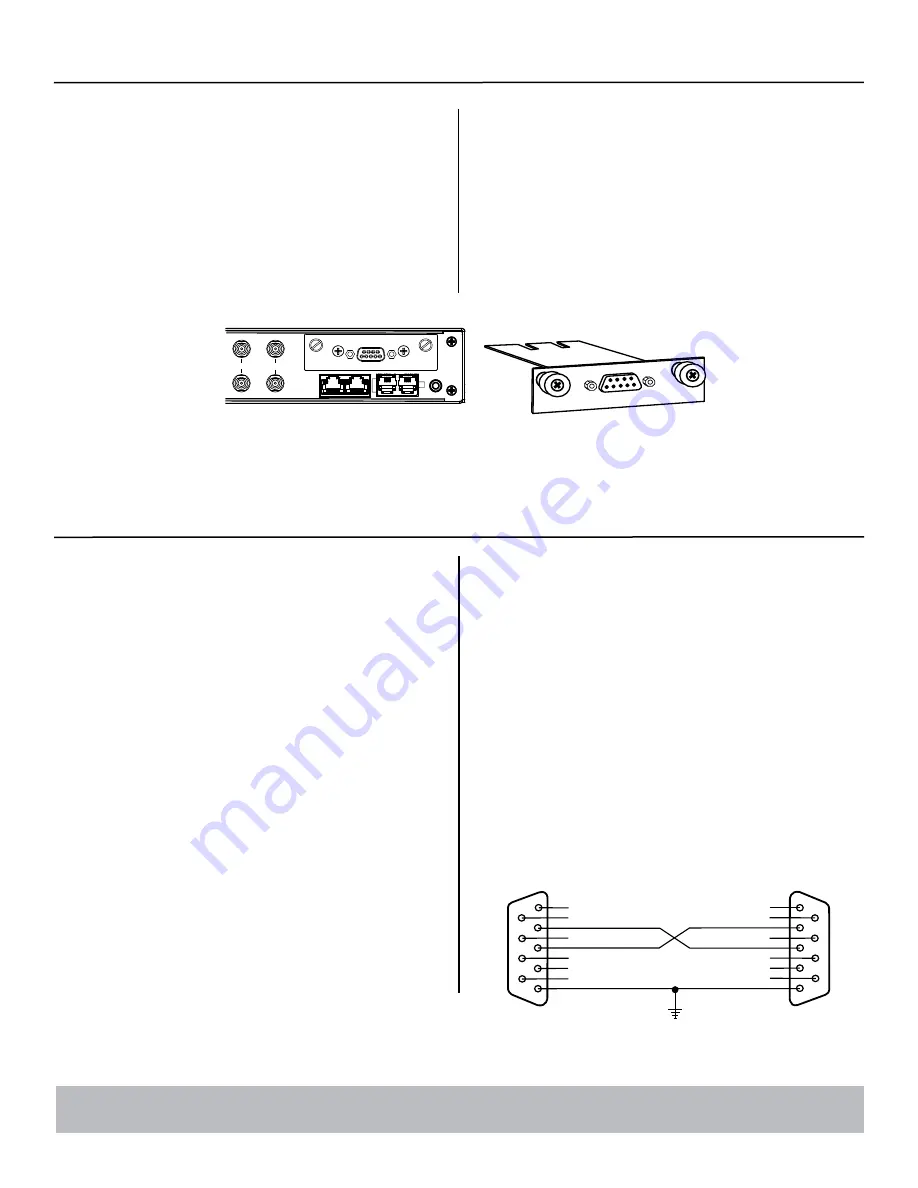
RS-232 Installation (optional)
It is recommended that you read the entire instructions list before proceeding. The
BlueBOLT-CV1 should already be factory installed in this Panamax M4315-PRO
component. To switch from BlueBOLT™ functionality to RS-232 connectivity,
follow these steps:
1.
Unplug M4315-PRO Power Management Component from AC wall outlet.
2.
If already connected,
unplug Ethernet cable from BlueBOLT-CV1 card.
3.
Remove the BlueBOLT-CV1 card using thumbscrews.
Note:
minimal torque
should be applied in removal of the existing card.
4.
Remove RS-232 card from protective packaging.
5.
Noting the two guiding channels within the card slot, gently slide the RS-232
card into the card slot, making sure to screw the thumbscrews down for a snug
and secure fit.
6.
Connect RS-232 cable (sold separately) to the RS-232 card to establish a
connection between the M4315-PRO Component and an RS-232 enabled Home
Theater control device.
7.
Plug in M4315-PRO Component to an AC wall outlet power receptacle.
1.2.1
QUERY:
A message sent to the M4315-PRO unit from the
controller requesting a status message to be returned.
Query strings start with a question mark (?, 3Fh, 63d).
1.2.2
RESPONSE:
A message sent from the M4315-PRO unit to
the controller indicating the current status. Response
strings start with a dollar sign ($, 24h, 36d).
1.2.3
The command prompt (>) is displayed when ready for next
command/query.
2. RS232 CONFIGURATION
2.1
Connector Type:
DB-9 Female
2.2
Connector Pin-out:
Pin 2, Transmit.
M4315-PRO transmits data on this pin.
Pin 3, Receive.
M4315-PRO receives data on this pin.
Pin 5, SG (signal ground).
CATV / SAT 1 CATV / SAT 2
LAN CAT 5e
TELCO
DC TRIGGER
RS232
IN
O
U
T
RS232
Command Set/Status Messaging
The following commands are applicable when communicating with your M4315-PRO via direct connection using Telnet protocol or the included RS-232 interface.


