5
GETTING SETUP For BlueBOLT
™
BlueBOLT Online Registration
Note:
Make sure to complete system setup #1 or # 2 before registering.
Step 1.
Log into
http://www.mybluebolt.com
for online registration.
Your BlueBOLT™ enabled M4315-PRO Power Management Component is
completely plug-and-play and does not require any software installation or
network configuration (including configuring of network ports).
The online BlueBOLT™ control interface is operated through your web browser.
Step 2.
Using any Internet connected computer go to www.mybluebolt.com
in your standard Internet browser. Please make sure your browser is up to date
with the latest software for best BlueBOLT interface performance.
Step 3.
Follow the on screen instructions to create an account and/or take
control of your BlueBOLT™ enabled product.
Note:
You will need the BlueBOLT-CV1’s unique
MAC ADDRESS
and
CHALLENGE
KEY
(duplicate labels provided in packaging on cover of Quick Start Guide as well
as on the card itself) in order to register the BlueBOLT™ device online.
Troubleshooting
• Is your Power Management Component receiving power? Check the power
cable and confirm the unit’s breaker is in the ON position.
• Is your BlueBOLT-CV1 card installed properly? The “Link” light should be
illuminated (solid green) and the “Activity” light should be blinking intermittently
(green).
• Is your Internet connection functioning? Can you access a general web page?
• Is your BlueBOLT-CV1 card connected to your internet router or modem?
Check the Ethernet cable and confirm that the unit is connected to an active
Internet connection, and make sure those connected devices are receiving
power.
• If you have answered “Yes” to all of these questions and are still unable to
connect your M4315-PRO component, please contact Panamax customer
service at 1-800-472-5555.
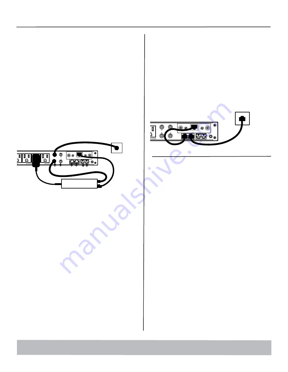
SYSTEM SETUP #1
Network Equipment Powered by M4315-PRO
(devices in same room)
Step 1.
Connect the power supply for the modem/router into the M4315-PRO.
Step 2.
Connect the coaxial line or telephone DSL line from the wall, to M4315-
PRO signal line pass-through protection circuits.
Step 3.
Route coaxial cable line or telephone DSL line from the M4315-PRO
back to modem/router’s input.
Step 4.
Plug in and switch on M4315-PRO.
SYSTEM SETUP #2
Network Equipment NOT-Powered by M4315-PRO
(devices in separate rooms)
Step 1.
Connect network Ethernet cable from PoE/network adapter or wall
plate to the Ethernet pass-through protection port on M4315-PRO.
Step 2.
Connect second Ethernet cable from pass-through protection port to
BlueBOLT-CV1 card.
Step 3.
Power on M4315-PRO. (Note: adding a device to your home/office
network may require a power cycle of the router/modem to
establish connection.
Once you input the
MAC ADDRESS
and included
CHALLENGE KEY
, if
BlueBOLT™ cannot detect your device (please allow up to 60 seconds),
please follow the on-screen troubleshooting guide. Also confirm an
Internet connection by accessing a general website –
example www.panamax.com.
GROUND
OUTLET 8 OUTLET 7 OUTLET 6 OUTLET 5 OUTLET 4 OUTLET 3 OUTLET 2 OUTLET 1
FILTER BANK 4 FILTER BANK 3 FILTER BANK 2 FILTER BANK 1
CATV / SAT 1 CATV / SAT 2
LAN CAT 5e
TELCO
DC TRIGGER
AC INLET
BlueBOLT-CV1
IN
O
U
T
MODEM / ROUTER
COAX LAN TEL
BlueBOLT
AC
AC
ETHERNET
CABLE
COAX CABLE
GROUND
OUTLET 8 OUTLET 7 OUTLET 6 OUTLET 5 OUTLET 4 OUTLET 3 OUTLET 2 OUTLET 1
FILTER BANK 4 FILTER BANK 3 FILTER BANK 2 FILTER BANK 1
CATV / SAT 1 CATV / SAT 2
LAN CAT 5e
TELCO
DC TRIGGER
AC INLET
BlueBOLT-CV1
IN
O
U
T
BlueBOLT
AC
ETHERNET
CABLE IN
FROM WALL
Advanced Operation
Besides providing access to Panamax/Furman’s hosted BlueBOLT platform,
the included BlueBOLT-CV1 card also supports the following networking
protocols:
• Telnet (default port 23), for interfacing to control and
automation systems within the local network.
• HTTP (web server at default port 80) for configuring the
network settings for stand-alone “static IP” operation.
For more information, see the application note BlueBOLT Advanced Net-
working, available online at www.mybluebolt.com.


