EmStat3-MUX8 for OEM
7
EmStat3-MUX8 for OEM
3.3
MUX8 configurations
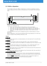
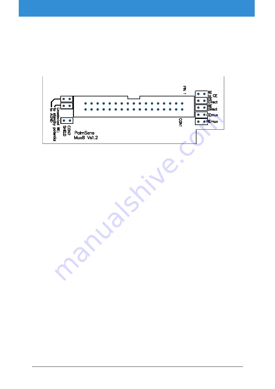
The multiplexer can be used in different configurations or modes. Each configuration is set by a
number of jumpers which are located on the board as shown in the illustration of the board layout
below.
Possible sensor configurations are:
Sensor arrays with (up to) eight working, reference and counter electrodes
Sensor arrays with eight working and eight combined reference/counter electrodes
Sensor arrays with eight working electrodes sharing a reference and a counter electrode
Sensor arrays with eight working electrodes sharing a combined reference/counter
electrode
In all configurations the sensors can be multiplexed, leaving the not-selected sensors or cells at
open circuit.
Sensor configurations 2, 3 and 4 have the possibility to leave not-selected sensors or cells at open
circuit or to apply the same potential to all sensors or cells.
Jumpers:
J1: RE to CE
Is placed when the sensor has a combined reference and counter electrode. This jumper therefore
connects RE to CE.
J2: CE Direct
If the sensor array has more than one working electrode, but one counter and/or reference
electrode, this jumper is placed. CE from PalmSens is connected directly to pin 1 and pin 2 of CON1
J3: RE Direct
If the sensor array has more than one working electrode, but one counter and/or reference, this
jumper is placed. RE from PalmSens is connected directly to pin 13 and 14 of CON1
J4: CE MUX
This jumper is placed if CE has to be multiplexed. This is the case when each of the sensors has its
own counter electrode using pin3 to 10.
J5: RE MUX
This jumper is placed if RE has to be multiplexed. This is the case when each of the sensors has its
own reference electrode using pin 15 to 22
J6: Unselected WE to AGND:
If placed, all unselected working electrodes or sensors will remain polarized at the potential set by
the PalmSens or EmStat. If this jumper is not placed only the selected channel is polarized leaving
the not-selected WE’s at open circuit.
When using Conf 1 and CE and RE are multiplexed (J4 and J5 are placed), this jumper is not
relevant since only the selected channel’s WE, CE and RE are polarized.
J7: Unselected WE to standby potential
See section 3.3

