Page 45
TU2506
ǀ
TU2807V
US
4.12
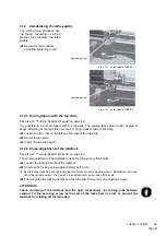
Immobilising the lathe saddle
The cutting force produced dur-
ing facing, recessing or slicing
process may displace the lathe
saddle.
Secure the lathe saddle
using the tightening screw.
Fig.4-15:
Lathe saddle TU2506
Fig.4-16:
Lathe saddle TU2807V
4.12.1 Turning tapers with the top slide
See also
"Turning Speeds & Feeds“ on page 48
It is possible to turn short tapers with the top slide. The scaling takes place to 60° degree of
angle. Adjusting of the top slide over the 60° angle mark outside is possible.
Loosen the two nuts on the left and the right of the top slide.
Swivel the top slide.
Clamp the top slide again.
4.12.2 Cross-adjustment of the tailstock
See also
"Turning Speeds & Feeds“ on page 48
The cross-adjustment of the tailstock is used for turning long, thin shafts.
Loosen the locking handle of the tailstock.
Unscrew the locking screw approximately half a turn.
By alternately loosening and tightening the two (front and rear) adjusting screws, the tailstock is moved
out of the central position. The desired cross-adjustment can be read off the scale.
First retighten the locking handle and then the two (front and rear) adjusting screws.
ATTENTION!
Check clamping of the tailstock and the quill, respectively, for turning jobs between
centres! Fit the securing screw at the end of the lathe bed in order to prevent the
tailstock from falling off the lathe bed.
tightening screw
tightening screw
Summary of Contents for TU 2506
Page 1: ...US Item No 9684509 Operating manual Version 2 2 2 Lathe...
Page 74: ...Page 74 TU2506 US...
Page 92: ...Page 92 TU2506 TU2807V US 8 Wiring diagrams 8 1 TU2506 Fig 8 1 Wiring diagram TU2506...
Page 93: ...Page 93 TU2506 TU2807V US 8 2 TU2807V 230V Fig 8 2 Wiring diagram TU2807V...
Page 98: ...Page 98 TU2506 TU2807V US...


