6
Palmgren Operating Manual & Parts List
9683311
OPERATION (CONTINUED)
•
Thickness average should be used when choosing a blade for
the optimum number of teeth in contact, however, the three
teeth rule should be applied to the minimum thickness, not
thickness average.
•
Keeping a selection of sharp blades on hand will yield better
cuts. Blades may last longer because they are less likely to be
misused when proper blade is available.
•
Every band saw should have at least one replacement blade of
each type used. Blade breakage is unpredictable. Consult a
blade manufacturer for detailed information about available
blades for specific uses.
REMOVING BLADE
Refer to Figure 10.
WARNING:
Disconnect band saw from power source when
changing or adjusting blades. Wear leather gloves when handling
band saw blades. Never wear gloves when operating saw.
1. Raise the head and open the blade cover.
2. Loosen the outer guide bearings on the upper and lower guide
assemblies. No other guide bearings should be moved.
3. With one hand, pinch the blade and the tracking wheel to-
gether to protect against the possibility of the blade popping
off when tension is released.
4. Release the tension by slowly revolving the knob (Ref. No. 181)
counterclockwise.
5. Remove the blade.
REPLACING THE BLADE
1. Make sure the outer guide bearings are loose.
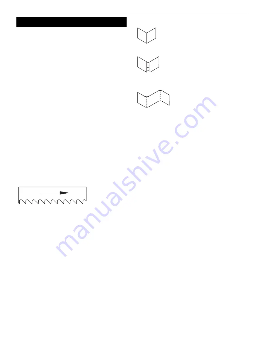
2. Make sure the teeth are pointing in the right direction
(See Figure 4).
3. Place the blade around the wheels and between the guide
bearings.
4. Hold the blade in position and apply tension.
5. Push the blade against the wheel flange.
6. Tighten the blade until it is properly tensioned. A properly
tightened blade will ring slightly when the back of the blade is
plucked (like a string of an instrument).
7. Adjust the outer guide bearings.
8. Check for proper tracking (See Tracking Adjustment).
TRACKING
Proper tracking is achieved when the drive wheel and tracking
wheel are aligned. A blade that is not tracking correctly can come
off the blade wheels. Although adjustment is rarely required, track-
ing should be checked frequently.
CAUTION:
Turn motor off and disconnect power to check tracking.
CHECK TRACKING
Refer to Figures 5 and 10.
1. Raise the head. Open the wheel cover.
2. Insert a piece of paper between the blade and the left side of
the idler wheel.
3. Let the blade grab the paper. Rotate the tracking wheel (Figure
10, Ref. No. 175) so the paper goes around the wheel.
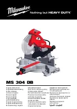
4. Refer to Figure 5 to determine if an adjustment is needed.
TRACKING ADJUSTMENT
Refer to Figures 5 and 10.
The tracking is adjusted by positioning the tracking wheel shaft
(Ref. No. 171). The positioning is done with the set screw (Ref. No.
167).
1. Loosen the two socket head bolts.
2. Adjust the tilt with set screws. For correct tracking, refer to
Figure 5. Turn 1/4 revolution at a time.
3. Check the blade tension and adjust if necessary.
4. Recheck the tracking.
5. Once the proper position has been found, tighten the bolts
securely.
BLADE SPEED
Choosing the proper blade speed is important for extending the
life of the blade. The speed determines the available cutting force.
•
Harder materials require more force and are cut at a slower
speed.
•
Softer materials are cut with less force at higher speeds to en-
sure the proper removal of the chips.
•
The speed and corresponding force are related to the power
supplied to the blade. Four speeds are available.
•
If a motor, other than the one supplied is used, the cutting
speeds will be changed.
•
Speeds and corresponding materials are listed below.
FPM
86 . . . . . . . . . . . . . . . . . . . . . . . . . . . . . . . . . . . . . . . Stainless steel, alloy steel
132 . . . . . . . . . . . . . . . . . . . . . Medium to high carbon steels, hard brass
178 . . . . . . . . . . . . . . . . . . . . . . . . Low to medium carbon steels, copper
260 . . . . . . . . . . . . . . . . . . . . . . . . . . . . . . . . . . . . . . . . . . . Aluminum, plastics
Figure 4 – Blade Direction
Figure 5 – Tracking Adjustments
A sharp fold
indicates proper tracking.
Cut or ripped paper indicates
that the blade is riding against
the flange of the wheel. Ad-
justing set screw needs to be
turned counterclockwise.
No fold indicates the blade will
ride off the wheel. Adjusting set
screw should be turned clockwise.


