background image

For technical support, provide the following model

and serial numbers:

Model No: ______________________

Serial No:  ______________________

14’’ BAND SAW    

owner’s MAnUAL

20-302

07

20

20

Summary of Contents for 20-302

Page 1: ...For technical support provide the following model and serial numbers Model No ______________________ Serial No ______________________ 14 BAND SAW owner s MAnUAL 20 302 072020 ...

Page 2: ...sentative will inspect repair or replace any part that has proven to be defective in workmanship or material provided that the customer sends the product prepaid to a designated authorized service center and provides reasonable time to proceed If judged on warranty the manufacturer or its representative will return the repaired product prepaid or will replace it by a new one at its choice On the c...

Page 3: ...time with no obligation to Steel City INTRODUCTION 3 TABLE OF CONTENTS 3 PRODUCT SPECIFICATIONS 3 SAFETY 4 PRODUCT SAFETY 6 ELECTRICAL AND GROUNDING INSTRUCTIONS 7 UNPACKING AND INVENTORY 8 ASSEMBLY 9 ADJUSTMENTS 11 MAINTENANCE 14 PARTS LIST 15 TABLe oF ConTenTs InTroDUCTIon ProDUCT sPeCIFICATIons Motor 1 HP 110V 1 ph 11A convertible to 220V 1 ph Motor speed 1720 RPM Blade speed 2300 or 3200 lin f...

Page 4: ... properly fitting NIOSH OSHA approved respiratory protection appropriate for the dust exposure and wash exposed areas with soap and water DAnGer This manual is not totally comprehensive It does not and can not convey every possible safety and operational problem which may arise while using this machine The manual will cover many of the basic and specific safety procedures needed in an industrial e...

Page 5: ...g the machine ON 21 MAInTAIn your balance Do noT extend yourself over the tool Wear oil resistant rubber soled shoes Keep floor clear of debris grease and wax 22 Do noT operate any machine or tool if under the influence of drugs alcohol or medication 23 MAInTAIn all machines with care ALwAYs KeeP the machine clean and in good working order KeeP all blades and tool bits sharp and free of all rust a...

Page 6: ... a blade break stop the machine imme diately et move away to avoid any part projection Wait until complete wheels stop before opening the access doors 3 While using do not bring your fingers any closer than 2 to the blade Use a push stick or pull the piece from behind the blade 4 Get rid of the waste parts as you go rather than letting them fall on the floor and risk to tip over them ...

Page 7: ... AWG 16 AWG 16 AWG 6 to 10 Amps 18 AWG 16 AWG 14 AWG 10 to 12Amps 16 AWG 16 AWG 14 AWG 12 to 15Amps 14 AWG 12 AWG Not recommended exTensIon CorDs PLUGs reCePTACLes MAKe sUre the circuit breaker does not exceed the rating of the plug and receptacle wArnInG To reduce the risk of fire or electrical shock use the proper gauge of extension cord When using an extension cord be sure to use one heavy enou...

Page 8: ...ainted surfaces will suffer Unpack the machine carefully and make an inventory of the hardware and accessories in the packaging referring to the list below Be aware of missing or damaged parts to inform your supplier as soon as possible wArnInG This machine is heavy more than one person is required to unpack and lift UnPACKInG InVenTorY 1 Band saw 2 Table 3 Stop paddle 4 Base end panels 5 Base sid...

Page 9: ...base and attach it to the base by using hex bolts on each corner 2 Install the step pulley on the motor shaft with the largest pulley on the motor side Put the key in the shaft keyway slide the pulley in and lock it in place by tightening the set screw 3 Install the motor on the saw Put the motor on the base and slide it in place by passing the pulley into the hole of the saw side 4 Put the motor ...

Page 10: ... slip on the pulley Secure the motor mount bolts back to the saw base 2300 F P M 3200 F P M Wheel pulley Motor pulley Step pulleys lower wheel removed for clarity ATTACHInG THe TABLe 1 Install the table mount on the saw frame using 2 hex bolts Also install the hex bolt and nut acting as positive stop at shown location near the table mount Stop 2 With the bolts hanging free through the trunnions gu...

Page 11: ...n spring To increase the tension turn the lever in vertical position in clockwise direction To reduce tension turn in counterclockwise direction Lower handle to apply tension and check if setting is appropriate Never turn the tension handle while it is in downward position as you may break the tension spring Increase tension Reduce tension To prolong the life of the blade and the spring if the ban...

Page 12: ...d after each blade replacement and after each blade tracking adjustment Also the upper guide block assembly must be adjusted to be about 1 8 3 mm above the piece Minimum amount of blade should be exposed With one hand loosen the knob securing the assembly in position and with the other hand raise or lower the guide block assembly to the proper height The friction blocks on each side of the blade m...

Page 13: ...out resting on a tooth of the blade 3 Measure the distance from the straightedge to the miter slot at each end of the table If these measurements are not equal slightly rotate the table to correct realign the straightedge with the blade and take measurements again from the miter slot to the straightedge at each end of the table 4 When both measurements are equal tighten the 6 trunnion bolts Be car...

Page 14: ...t do not use acetone or lacquer thinner Lubricate using lubricant for dusty environment Threaded parts and mobile parts should be inspected cleaned and lubricated regularly to prevent malfunctioning DrIVe BeLT rePLACeMenT 1 Release blade tension 2 Remove the blade 3 Remove the nut and washer from the center of the wheel Untighten the nut by turning in clockwise direction CLeAnInG BrUsH A cleaning ...

Page 15: ...Page 15 PArTs LIsT ...

Page 16: ...Page 16 ...

Page 17: ...Page 17 ...

Page 18: ...Page 18 ...

Page 19: ...Page 19 ...

Page 20: ...Page 20 u noTes u ...
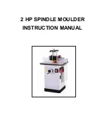
Reviews: